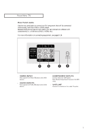
Samsung CL-17M2MQ User Manual (user Manual) (ver.1.0) (English) - Page 12
After you've made this connection, set the A/B switch to the A position for normal view
 |
View all Samsung CL-17M2MQ manuals
Add to My Manuals
Save this manual to your list of manuals |
Page 12 highlights
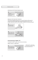
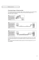
INSTALLATION 5 Connect another cable between the other OUT terminal on the splitter and the A-IN terminal on the RF (A/B) switch. Incoming Cable Splitter Cable Box RF (A/B) Switch 6 Connect the last coaxial cable between the OUT terminal on the RF (A/B) switch and the VHF/UHF terminal on the back of the TV. Incoming Cable Splitter Cable Box RF (A/B) Switch ANT IN TV Rear After you've made this connection, set the A/B switch to the "A" position for normal viewing. Set the A/B switch to the "B" position to view scrambled channels. (When you set the A/B switch to "B", you will need to tune your TV to the cable box's output channel, which is usually channel 3 or 4.) 12
-
 1
1 -
2
-
3
-
4
-
5
-
6
-
 7
7 -
 8
8 -
 9
9 -
 10
10 -
 11
11 -
 12
12 -
 13
13 -
 14
14 -
 15
15 -
 16
16 -
 17
17 -
18
-
19
-
20
-
21
-
22
-
23
-
24
-
25
-
26
-
27
-
28
-
29
-
30
-
31
-
32
-
33
-
34
-
35
-
36
-
37
-
38
-
39
-
40
 |
 |

12
I
NSTALLATION
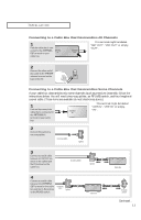
5
Connect another cable
between the other OUT
terminal on the splitter
and the A–IN terminal on
the RF (A/B) switch.
ANT IN
6
Connect the last coaxial
cable between the OUT
terminal on the RF (A/B)
switch and the VHF/UHF
terminal on the back of
the TV.
After you’ve made this connection, set the A/B switch to the “A” position for normal view-
ing. Set the A/B switch to the “B” position to view scrambled channels. (When you set the
A/B switch to “B”, you will need to tune your TV to the cable box’s output channel, which is
usually channel 3 or 4.)
Incoming
Cable
Cable Box
RF (A/B)
Switch
Splitter
Incoming
Cable
Cable Box
RF (A/B)
Switch
TV Rear
Splitter