Samsung LN-R1550P Quick Guide (easy Manual) (ver.1.0) (English) - Page 14
Connecting a PC, After you've made this connection, set the A/B switch to the A position for normal
 |
View all Samsung LN-R1550P manuals
Add to My Manuals
Save this manual to your list of manuals |
Page 14 highlights
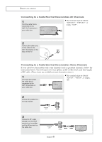
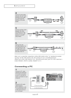
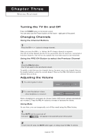
I N S TA L L AT I O N 4 Connect an RF cable between the ANT OUT terminal on the cable box and the B-IN terminal on the A/B switch. Incoming cable Splitter Cable Box RF (A/B) Switch 5 Connect another cable between the other OUT terminal on the splitter and the A-IN terminal on the RF (A/B) switch. Incoming cable Splitter Cable Box RF (A/B) Switch 6 Connect the last RF cable between the OUT terminal on the RF (A/B) switch and the ANT IN terminal on the rear of the TV. Incoming cable Splitter Cable Box RF (A/B) Switch ANT IN TV Rear After you've made this connection, set the A/B switch to the "A" position for normal viewing. Set the A/B switch to the "B" position to view scrambled channels. (When you set the A/B switch to "B", you will need to tune your TV to the cable box's output channel, which is usually channel 3 or 4.) Connecting a PC 1 Connect a PC video cable(D-Sub) between PC IN [PC] connector on the TV and the PC output connector on your computer. 2 Connect a PC audio cable between PC IN [AUDIO] on the TV and the Audio Out of the sound card on your computer. PC Audio Cable (Option) PC Video Cable (Option) English-9 TV Rear Panel
-
 1
1 -
2
-
3
-
4
-
5
-
6
-
7
-
8
-
 9
9 -
 10
10 -
 11
11 -
 12
12 -
 13
13 -
 14
14 -
 15
15 -
 16
16 -
 17
17 -
 18
18 -
 19
19 -
20
-
21
-
22
-
23
-
24
-
25
-
26
-
27
-
28
-
29
-
30
-
31
-
32
-
33
-
34
-
35
-
36
-
37
-
38
-
39
-
40
-
41
-
42
-
43
-
44
-
45
-
46
-
47
-
48
-
49
-
50
-
51
-
52
-
53
-
54
-
55
-
56
-
57
-
58
-
59
-
60
-
61
-
62
-
63
-
64
-
65
-
66
-
67
-
68
 |
 |
