Sanyo EM-U1000W Service Manual
Sanyo EM-U1000W - Compact Microwave,10 Pwr Lvls,800 W,18"x14-3/8"x11-5/8",WE Manual
 |
UPC - 086483046926
View all Sanyo EM-U1000W manuals
Add to My Manuals
Save this manual to your list of manuals |
Sanyo EM-U1000W manual content summary:
- Sanyo EM-U1000W | Service Manual - Page 1
Model: EM-U1000W/B Microwave Oven Service Manual REFERENCE NO. SM1500006 - Sanyo EM-U1000W | Service Manual - Page 2
17 SPOT EXAMINING STEPS OF THE MICROWAVE OVEN 15 1.18 REPAIRING METHOD OF SEVERAL BREAKDOWN 18 1.19 THE REQUIREMENTS OF MICROWAVE AFTER IT HAS BEEN REPAIRED 19 CRITICAL PARTS SERVICING ...20 1.20 IMPORTANT THINGS TO DO PRIOR TO CRITICAL PARTS SERVICING 20 1.21 Interlock Assembly Replacement and - Sanyo EM-U1000W | Service Manual - Page 3
components in the interlock, monitor, door seal and microwave generation and transmission systems shall be repaired, replaced, or adjusted by procedures described in this manual before the oven is released to the owner. E. A microwave leakage check to verify compliance with the Federal performance - Sanyo EM-U1000W | Service Manual - Page 4
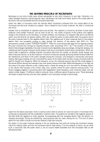
that the polar molecule would produce heat due to somewhat similar friction among them. When the electric field is applied for ultrahigh frequent microwave field from the outside, its direction would change tens billion times per second, so do the molecule. This kind of molecule swaying producing - Sanyo EM-U1000W | Service Manual - Page 5
microwave generator, the generator stars working to transfer the microwave energy to the heating chamber for heating food through wave guide part of the widely used model, mechanical control and touch control microwave oven. 1.1 HIGH VOLTAGE RECTIFYING CIRCUIT At present, home use microwave oven - Sanyo EM-U1000W | Service Manual - Page 6
models and rate output of the magnetron, compelling wind cooling and flowing water-cooling can be adopted. Usually, the home used microwave oven adopts directly to the glass part of the magnetron to avoid blasting. 1.4 ELECTRIC CONTROL SYSTEM In mechanical control microwave ovens, electric control - Sanyo EM-U1000W | Service Manual - Page 7
(S3) which is still at conducted condition, the monitor switch would immediately make the 120V voltage short-circuited and blow up the fuse, and will never let the microwave oven working when the door is open. From this we can understand the function of the interlock switch is when the door is - Sanyo EM-U1000W | Service Manual - Page 8
window 3. Air vent 4. Roller Shaft 5. roller ring 6. Glass tray 7. control panel To improve the heating evenness there often fixed a turntable glass tray at the bottom of the cavity (FIG. 2-8). It is through changing the relative place of the microwave and the heating matter to improve the heating - Sanyo EM-U1000W | Service Manual - Page 9
circuit of the microwave oven link with the practical circuit at this chapter. SCHEMATIC DIAGRAM NOTE: Door is closed Unit is not operated L 120V 60Hz FUSE MONITOR SWITCH THERMAL CUTOUT (MAG.) (OVEN) N SECONDARY SWITCH PRIMARY SWITCH POWER RELAY C OVEN LAMP L FAN MOTOR TURNTABLE MOTOR FM - Sanyo EM-U1000W | Service Manual - Page 10
diagram of computer controlled microwave ovens: Circuit diagram for mechanical controlled microwave ovens: HOW TO ASSEMBLE AND DISASSEMBLE MICROWAVE OVEN COMPONENTS In the following pages, we will introduce the ways in which the various parts of a typical microwave oven can be disassembled and - Sanyo EM-U1000W | Service Manual - Page 11
left hinge (up) with a socket wrench (FIG.4 - 2). 4. Push the door release button to have the hook out (FIG.4 -3). hinge(up) oven 5. Pull the hinge with the door out of the oven together, and take off the washer of the hinge (low) shaft (FIG.4 - 2). 6. Pick up the ten inverse hooks, which around - Sanyo EM-U1000W | Service Manual - Page 12
cause large amount of microwave leakage. Attention : When a new oven matches a magnetron, the lacquer layer around the "★"mark should be polished with sand paper till metal luster shines through. (FIG.4 -7). 2. Aim the head of the magnetron antenna to the hole of the wave guide housing, tighten the - Sanyo EM-U1000W | Service Manual - Page 13
this part. Dismantling steps for the transformer: (as FIG.4 -9). 1. Pull out all the terminal of the transformer. 2. Turn the microwave over baseboard, the seat and the rubber space between the transformer and the oven. screw base board transformer seat Fig.4-9 Fig.4-10 to mount the transformer - Sanyo EM-U1000W | Service Manual - Page 14
, and tighten the screws as FIG.4 - 11 and FIG.4 - 12. fuse housing earthing screw power supply cord Fig.4-12 fan motor back board fan Fig.4- 12 THE DIOD Firstly, do as the 1, 2, and 3 steps of Ⅲ of this part. To disassemble, 1. Pull out the diode plug, which plugged in the capacitor. 2. Loosen - Sanyo EM-U1000W | Service Manual - Page 15
the oven back. 5. As the FIG.4 - 19 shown, fix in the turntable shaft supporter, the place in the roller ring and the glass tray as FIG .4 - 20. turntable shaft supporter roller ring Fig.4-18 Fig.4-19 1.14 THE DOOR SAFETY INTERLOCKS Firstly, do as the same with 1, 2, 3, steps of Ⅲ of this part - Sanyo EM-U1000W | Service Manual - Page 16
loose is at lower part of the door, the adjust methods is the same with the above said steps but the screw is the one below (FIG.4 - 21). screw latch switch hold front door pla Fig.4-21 1.15 THE CONTROL PANEL OF A TYPICAL MICROWAVE OVEN Pull out the power plug. light tough switch Take - Sanyo EM-U1000W | Service Manual - Page 17
over-working would be done when repair. The microwave oven may occur compound breakdown due to part short - circuited. 1.17.3 EXAMINATION OF MICROWAVE LEAKAGE Measure the microwave leakage with a microwave leakage measure. Place a graduate of 275ml water at the middle of the glass tray of the oven - Sanyo EM-U1000W | Service Manual - Page 18
microwave leakage of all the measure position should not exceed 1 milliwatt/cm2, of should be considered as abnormal. 1.17.4 EXAMINE WHEN THE OVEN AT OPERATING, BUT THE FOOD CAN'T BE HEATED Fig.5-3 (1) Examine when the lamp is on, the glass tray If there is no problem with the magnetron, check - Sanyo EM-U1000W | Service Manual - Page 19
1.17.5 EXAMINE THE STARTING AND THE 8A FUSE OF THE MICROWAVE OVEN Pull out the power plug, take off the magnetron, it indicates the magnetron magnetron has broken, and should be replaced by a new, same model one. If the magnetron is also normal, then test the pilot switch. Pull out the two - Sanyo EM-U1000W | Service Manual - Page 20
repairing, check whether the above listed point are existed, if not, can you start the microwave oven. Place a graduate of about 275ml water at the middle of the glass tray the oven. Then measure again, the door pushing part guide housing coupling has been oxidized or have lacquer on it. If do - Sanyo EM-U1000W | Service Manual - Page 21
a new, same model one. 1.19 THE REQUIREMENTS OF MICROWAVE AFTER IT HAS BEEN REPAIRED After being repaired, the microwave oven should have a turntable glass tray of the oven, insert the power plug, close the door, power set high, time set 3 minutes to make the oven in operation. Rectify the microwave - Sanyo EM-U1000W | Service Manual - Page 22
1.19.4 MICROWAVE DEFROST Place a graduate of about 200ml water on the turntable glass tray of the oven, power set middle, time set 4 minutes to make the oven operating in normal. When the bell of the time ring, open the door. It would be normal if the water is lukewarm. CRITICAL PARTS SERVICING 1.20 - Sanyo EM-U1000W | Service Manual - Page 23
COMMON BREAKDOWN OF MICROWAVE OVEN AND MEANS OF REPAIRING PHENOMENON 1. When starting the oven, the lamp is not on, the turntable tray can't rotate and the food can't be heated 2.When starting the oven, the lamp is on, the turntable rotating, the fan cycling but the food can't be heated. 3. The - Sanyo EM-U1000W | Service Manual - Page 24
guide connection oxidized The magnetron copper filament washer is too thin cause the wave guide repair it or change megaohms. those damaged components. SPECIFICATIONS Power Consumption: Microwave Power Output: Operation Frequency: Outside Dimensions(H×W×D): Oven Cavity Dimensions(H×W×D): Oven - Sanyo EM-U1000W | Service Manual - Page 25
MICROWAVE OVEN EXPLODED DRAWING EM-U1000BW Parts & Components List PART NO. COMPONENT CODE NO. Name QTY C01 GA-EM-U1000C01 P.C board 1 C02 GA-EM-U1000C02 turntable motor 1 GA-EM-U1000W03 power cord 1 C03 GA-EM-U1000C03 power cord 1 C04 GA-EM-U1000C04 wire harness 1 C05 GA-EM-U1000C05 - Sanyo EM-U1000W | Service Manual - Page 26
sheet 1 P44 GA-EM-U1000P44 packing belt 1 P22 GA-EM-U1000P22 shaft 1 P45 GA-EM-U1000P45 packing nail 8 P23 GA-EM-U1000P23 glass tray 1 P46 GA-EM-U1000P46 Pc board holder 1 P24 GA-EM-U1000P24 turntable support 1 P47 GA-EM-U1000W47 Outer enclosure 1 P25 GA-EM-U1000P25 choke cover 1 P47
-
 1
1 -
 2
2 -
 3
3 -
 4
4 -
 5
5 -
 6
6 -
 7
7 -
8
-
9
-
10
-
11
-
12
-
13
-
14
-
15
-
16
-
17
-
18
-
19
-
20
-
21
-
22
-
23
-
24
-
25
-
26
 |
 |

Model: EM-U1000
W/
B
Microwave Oven
Service Manual
REFERENCE NO.
SM1
5
00006