Sanyo EM-U1000W Service Manual - Page 22
Critical Parts Servicing - repair
 |
UPC - 086483046926
View all Sanyo EM-U1000W manuals
Add to My Manuals
Save this manual to your list of manuals |
Page 22 highlights
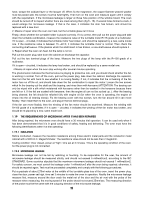
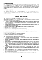
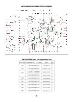
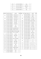
1.19.3 MICROWAVE HEATING Place a graduate of about 250ml water on the turntable tray. Close the door, power set high, time set 4 minutes (To those 700W microwave oven) to make the oven operating in normal. When the bell of the timer rings, open the oven door, the water should have boiled. If it have not been boiled yet, but is very hot, check whether the voltage is less than 120V. If the voltage below 120V but the water can be boiled after a little more time beating, it is normal. 1.19.4 MICROWAVE DEFROST Place a graduate of about 200ml water on the turntable glass tray of the oven, power set middle, time set 4 minutes to make the oven operating in normal. When the bell of the time ring, open the door. It would be normal if the water is lukewarm. CRITICAL PARTS SERVICING 1.20 IMPORTANT THINGS TO DO PRIOR TO CRITICAL PARTS SERVICING The following instructions are CRITICAL to the owner's safety. Be sure to follow all the instructions. Contact the manufacturer or distributor if you have any question. 1. If the oven is operative prior to servicing, a Microwave Leakage Test (a. k. a. Microwave Emission Check) should be performed prior to servicing the oven Refer to Section 7.3, Microwave Leakage Test. For the detailed check procedures. 2. In the event that any microwave oven found to have microwave emission level in excess of 4 mW/cm2. The following procedures should be followed: (1). .Inform the distributor; importer, or manufacturer the finding. Record it in the logbook as well. (2). .Repair the unit at no cost to the owner. (3). .Investigate the oven and ascertain the cause of the excessive leakage. (4). .Hold the oven in your facility and instruct the owner not to use the unil until the oven has. 3. In the event that the oven operates with the door open. The following procedures should be followed: (1). Tell the user not to operate the oven. (2). Hold the oven in your facility until it is investigated and repaired. (3). Contact the manufacturer and CDRH (FDA) immediately. 1.21 INTERLOCK ASSEMBLY REPLACEMENT AND ADJUSTMENT 1. If you suspect defective primary, secondary or monitor interlock switches, use your ommeter (digital or analog type) to check the electrical continuity. 2. Make sure the power cord is pulled out and the high-voltage capacitor is discharged before the electrical continuity check. 3. Set the ohmmeter to "Low Resistance" range and connect both leads (alligator clips) to the switch terminals. 4. Open the door and notice the meter reading the primary or secondary interlock switch should show an "infinite" resistancc when the door is open. Replace it when it is defective. The monitor interlock should show a "zero or near zero" resistance when the door is open. When the door is closed, the readings will be opposite. 5. If the oven has been rendered inoperative due to the failure of the monitored safety (primary and /or secondary ) interlock(s). You should replace all of the monitored safety interlock switched and the monitor switch. 6. Refer to Chapter 4, Sections I and X for how to remove and assemble the interlock and monitor switches. 7. Always refer to Section 0.4 for adequate wiring diagram. Monitor interlock must always be installed. Repeat Step 6.2.4 to check electrical continuity. 8. Perform required checks and tests as described in Chapter 7 before releasing the oven to the owner. 20
-
 1
1 -
2
-
3
-
4
-
5
-
6
-
7
-
8
-
9
-
10
-
11
-
12
-
13
-
14
-
15
-
16
-
 17
17 -
 18
18 -
 19
19 -
 20
20 -
 21
21 -
 22
22 -
 23
23 -
 24
24 -
 25
25 -
 26
26
 |
 |