Sanyo Em-z2000s Service Manual - Page 16
The Capacitor., The Diode.
 |
UPC - 086483045615
View all Sanyo Em-z2000s manuals
Add to My Manuals
Save this manual to your list of manuals |
Page 16 highlights
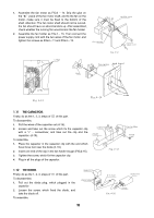
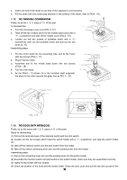
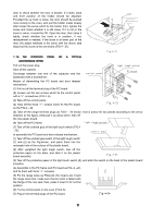
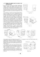
1. Assemble the fan motor as FIG.4 - 14. Drip the glue on the "★"place of the fan motor shaft, and fix the fan on the motor, make sure it must be fixed to the bottom of the shaft. Attention: The fan motor shaft should not be curved, the fan should have no abnormal stick up. After assembled, check whether the running fan would knock the fan holder. 2. Assemble the fan holder as FIG.4 - 13, Then connect the power supply cord with the two wires of the fan motor, and tighten the screws as FIG.4 - 11 and FIG.4 - 12. fuse housing earthing screw power supply cord Fig.4-12 fan motor back board fan Fig.4-13 Fig.4-14 screw 1.11 THE CAPACITOR. Firstly, do as the 1, 2, 3, steps of Ⅲ of this part. To disassemble, 1. Pull the wires of the capacitor out (4-15). 2. Loosen and take out the screw which fix the capacitor clip with a "+" - screwdriver, and take out the clip and the capacitor. (4-15). To assemble, 1. Place the capacitor in the capacitor clip with the end which have three foot near the diode (4-16). 2. Insert one end of the clip in the fan holder trough (FIG.4-15). 3. Tighten the screw, which fix the capacitor clip. 4. Plug in all the plugs of the capacitor. capacitor diode Fig.4-15 fan holder screw 1.12 THE DIODE. Firstly, do as the 1, 2, 3, steps of Ⅲ of this part. To disassemble, 1. Pull out the diode plug, which plugged in the capacitor. 2. Loosen the screw, which fixed the diode, and take the diode off. To assemble, magnetron transformer 15 H.V.fuse capacitor Fig.4-16 diode
-
 1
1 -
2
-
3
-
4
-
5
-
6
-
7
-
8
-
9
-
10
-
 11
11 -
 12
12 -
 13
13 -
 14
14 -
 15
15 -
 16
16 -
 17
17 -
 18
18 -
 19
19 -
 20
20 -
 21
21 -
22
-
23
-
24
-
25
-
26
 |
 |
