Sanyo PLC XU50 Owners Manual - Page 18
Connecting to video equipment, Terminals, of the Projector, Cables used for connection - reset
 |
View all Sanyo PLC XU50 manuals
Add to My Manuals
Save this manual to your list of manuals |
Page 18 highlights
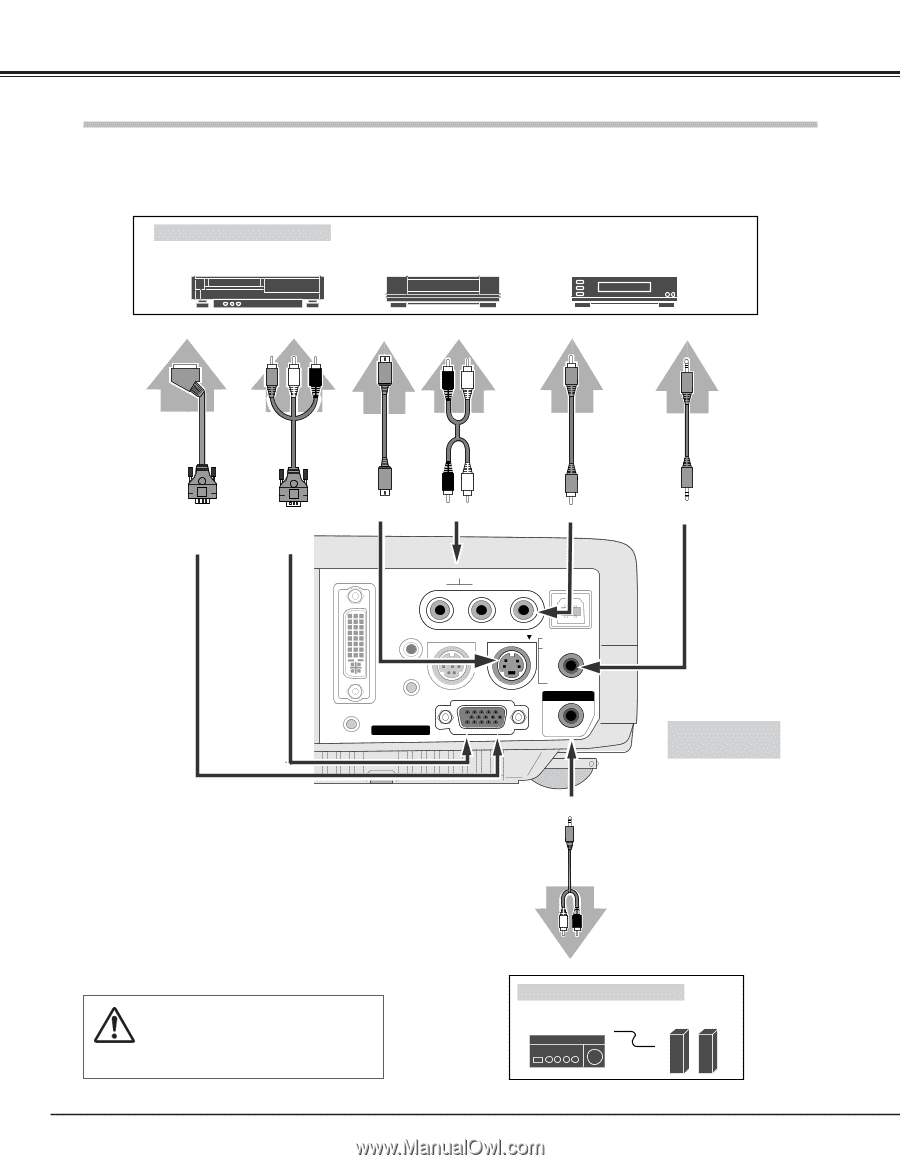
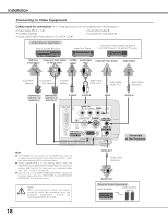
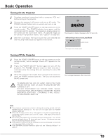
Installation Connecting to Video Equipment Cables used for connection (✽ = These accessories are not supplied with this projector.) • Video Cable (RCA x 1) ✽ • S-VIDEO Cable ✽ • Audio Cables (Mini Plug (stereo) x 2 or RCA x 2) ✽ • Scart-VGA Cable ✽ • Component-VGA Cable ✽ Video Source (example) Video Cassette Recorder Video Disc Player Component video output equipment. (such as DVD player or high-definition TV source.) RGB Scart Component Video Output S-VIDEO Audio Output Composite Video Output 21-pin Output (Y, Pb/Cb, Pr/Cr) Output (R, L) Audio Output Scart-VGA Cable ✽ ComponentVGA Cable ✽ S-VIDEO Cable ✽ Audio Cable (RCA x 2) ✽ Video Cable (RCA x 1) ✽ Audio Cable (Stereo) ✽ COMPUTER IN 2 / COMPONENT IN/ MONITOR OUT COMPUTER IN 2 / COMPONENT IN/ MONITOR OUT S-VIDEO AUDIO IN VIDEO COMPUTER IN 1 DVI - I AUDIO IN R L (MONO) VIDEO USB SERVICE PORT S-VIDEO COMPUTER / COMPONENT RESET MCI COMPUTER IN 2 / COMPONENT IN / MONITOR OUT AUDIO IN AUDIO OUT (VARIABLE) AUDIO IN Terminals of the Projector NOTE G The S-VIDEO jack has priority over the VIDEO jack under the condition of connecting both the S-VIDEO jack and the VIDEO jack when selecting AUTO in the Input Menu. G Select COMPUTER 2 in the Setting Menu when the COMPUTER IN 2/COMPONENT IN/MONITOR OUT terminal is used as RGB Scart 21-Pin video input or Component video input. (See "Terminal" on page 39.) G Input sound to the COMPUTER/COMPONENT AUDIO IN terminal when using the COMPUTER IN 2/COMPONENT IN/MONITOR OUT terminal as input. NOTE : When connecting the cable, the power cords of both the projector and the external equipment should be disconnected from AC outlet. AUDIO OUT Audio Cable (Stereo) ✽ Audio Input External Audio Equipment Audio Amplifier Audio Speaker (stereo) 18
-
 1
1 -
2
-
3
-
4
-
5
-
6
-
7
-
8
-
9
-
10
-
11
-
12
-
 13
13 -
 14
14 -
 15
15 -
 16
16 -
 17
17 -
 18
18 -
 19
19 -
 20
20 -
 21
21 -
 22
22 -
 23
23 -
24
-
25
-
26
-
27
-
28
-
29
-
30
-
31
-
32
-
33
-
34
-
35
-
36
-
37
-
38
-
39
-
40
-
41
-
42
-
43
-
44
-
45
-
46
-
47
-
48
-
49
-
50
-
51
-
52
-
53
-
54
-
55
-
56
 |
 |