Sanyo WF20 Instruction Manual, PLV-WF20 - Page 11
Terminals and Connectors, R/C JACK, USB CONNECTOR Series B, S-VIDEO INPUT JACK
 |
UPC - 086483069918
View all Sanyo WF20 manuals
Add to My Manuals
Save this manual to your list of manuals |
Page 11 highlights
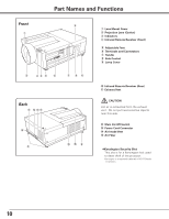
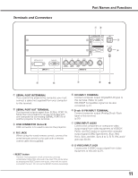
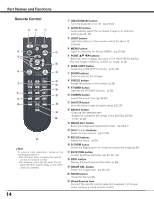
Terminals and Connectors Part Names and Functions qw e r t y u i ✽ q SERIAL PORT IN TERMINAL If you control the projector by computer, you must connect a cable (not supplied) from your computer to this terminal. w SERIAL PORT OUT TERMINAL This terminal outputs signal from SERIAL PORT IN. More than two projectors can be controlled with one computer by connecting SERIAL PORT IN of another projector to this terminal. e USB CONNECTOR (Series B) USB connector is to used to service the projector. r R/C JACK When using the wired remote control, connect the wired remote control to this jack with a remote control cable (not supplied). [ RESET button A built-in micro processor which controls this unit may occasionally malfunction and need to be reset. This can be done by pressing the RESET button with a pen, which will shut down and restart the unit. Do not use the RESET function excessively. t DVI INPUT TERMINAL Connect computer output (Digital/DVI-D type) to this terminal. (Refer to p.20) HD (HDCP Compatible) signal can be also connected. (p.21) y D-sub 15-PIN INPUT TERMINAL Connect computer output (Analog D-sub 15-pin type) to this terminal. (p.20) u 5 BNC INPUT JACKS Connect the component or composite video output signal from video equipment to VIDEO/Y, Pb/Cb, and Pr/Cr jacks or connect the computer output signal (5 BNC Type [Green, Blue, Red, Horiz. Sync, and Vert. Sync.]) to G, B, R, H/V, and V jacks (pp.20-21). i S-VIDEO INPUT JACK Connect the S-VIDEO output signal from video equipment to this jack (p.21). 11
-
 1
1 -
2
-
3
-
4
-
5
-
 6
6 -
 7
7 -
 8
8 -
 9
9 -
 10
10 -
 11
11 -
 12
12 -
 13
13 -
 14
14 -
 15
15 -
 16
16 -
17
-
18
-
19
-
20
-
21
-
22
-
23
-
24
-
25
-
26
-
27
-
28
-
29
-
30
-
31
-
32
-
33
-
34
-
35
-
36
-
37
-
38
-
39
-
40
-
41
-
42
-
43
-
44
-
45
-
46
-
47
-
48
-
49
-
50
-
51
-
52
-
53
-
54
-
55
-
56
-
57
-
58
-
59
-
60
-
61
-
62
-
63
-
64
-
65
-
66
-
67
-
68
-
69
-
70
-
71
-
72
-
73
-
74
-
75
-
76
-
77
-
78
-
79
-
80
-
81
-
82
-
83
-
84
 |
 |
