Schwinn 201 Recumbent Bike Assembly Manual - Page 10
Assembly, Stage
 |
View all Schwinn 201 Recumbent Bike manuals
Add to My Manuals
Save this manual to your list of manuals |
Page 10 highlights
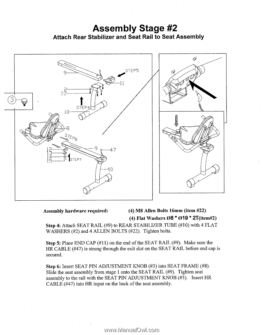
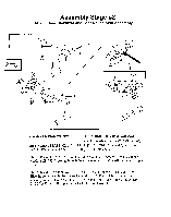
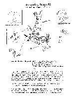
Assembly Stage #2 Attach Rear Stabilizer and Seat Rail to Seat Assembly 2 2 2-- t STEP4 1- 141 0 4 STEPS 1 1 1 9 7 1 1 STEP7 10 Assembly hardware required: (4) M8 Allen Bolts 16mm (item #22) (4) Flat Washers 08 * 019 * 2T(item#2) Step 4: Attach SEAT RAIL (#9) to REAR STABILIZER TUBE (#10) with 4 FLAT WASHERS (#2) and 4 ALLEN BOLTS (#22). Tighten bolts. Step 5: Place END CAP (#11) on the end of the SEAT RAIL (#9). Make sure the HR CABLE (#47) is strung through the exit slot on the SEAT RAIL before end cap is secured. Step 6: Insert SEAT PIN ADJUSTMENT KNOB (#3) into SEAT FRAME (#8). Slide the seat assembly from stage 1 onto the SEAT RAIL (#9). Tighten seat assembly to the rail with the SEAT PIN ADJUSTMENT KNOB (#3). Insert HR CABLE (#47) into HR input on the back of the seat assembly.
-
 1
1 -
2
-
3
-
4
-
 5
5 -
 6
6 -
 7
7 -
 8
8 -
 9
9 -
 10
10 -
 11
11 -
 12
12 -
 13
13 -
 14
14 -
 15
15 -
16
 |
 |