Schwinn Force Home Gym Assembly Manual - Page 8
Step 3, Attach the Rail Assembly to the Lat Tower, Step 4, Attach Chest Bar w/ Pulleys to Main
 |
View all Schwinn Force Home Gym manuals
Add to My Manuals
Save this manual to your list of manuals |
Page 8 highlights
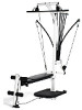
6 Assembly Guide Step 3: Attach the Rail Assembly to the Lat Tower Locate the following items: • From Step 1 - Lower Lat Tower and Base Frame Assembly • From Step 2 - Rail Assembly • Item #5 - Rail Knob • Item #H - (1) 3/8" X 4 1/2" Button Head Screws • Item #L - (2) 3/8" Washers • Item #M - (1) 3/8" Nylock Nuts Remove the twist ties from the pivot bushings prior to commencing this step. Line up the Lower Lat Tower (Item #2) with the Rail (Item #3) as shown in Figure 3. Pull out the locking pin on the Rail before you slide the Rail into the pivot bracket. Release the locking pin to lock into place. Then loosely install the Rail Knob (Item #5) into the pivot bracket on the Lower Lat Tower as shown in Figure 3. Place (1) 3/8" Washer (Item #L) over the end of (1) 3/8" X 4 1/2" Button Head Screw (Item #H) and slide the screw through the Lat Tower and Rail. Secure by placing (1) 3/8" Washer and (1) 3/8" Nylock Nut over the end of the screw. Tighten all hardware from this step. Step 4: Attach Chest Bar w/ Pulleys to Main Assembly Locate the following items: • From Step 3 - Main Assembly (Base Frame Assembly with Lower Lat Tower Assembly) • Item #6 - Chest Bar with Pulleys and Rod Cables • Item #F - (2) 3/8" X 2 3/4" Button Head Screws • Item #L - (4) 3/8" Washers • Item #M - (2) 3/8" Nylock Nuts The Chest Bar with Pulleys is the bar with the Rod Hook wrapped in the bag with the Pulley and Cable. Line up the holes in the Chest Bar with Pulleys and Rod Cables (Item #6) with the holes in the Lower Lat Tower (Item #2), as shown in Figure 4. Place (2) 3/8" Washers (Item #L) over the ends of (2) 3/8" X 2 3/4" Button Head Screws (Item #F) - one washer per screw. Slide the screws through the holes in the Lower Lat Tower and Chest Bar with Pulleys and Rod Cables. Place (2) 3/8" Washers and (2) 3/8" Nylock Nuts (Item #M) over the ends of the screws (one each per screw), as shown in Figure 4 and tighten. Figure 3 3 Figure 4 Rod Hook 2 5 L H M Locking Pin 1 F Locking Pin 6 L M
-
 1
1 -
2
-
 3
3 -
 4
4 -
 5
5 -
 6
6 -
 7
7 -
 8
8 -
 9
9 -
 10
10 -
 11
11 -
 12
12 -
 13
13 -
14
-
15
-
16
-
17
-
18
-
19
-
20
 |
 |
