Schwinn IC Pro Indoor Cycling Bike Assembly Manual - Page 6
Assembly
 |
View all Schwinn IC Pro Indoor Cycling Bike manuals
Add to My Manuals
Save this manual to your list of manuals |
Page 6 highlights
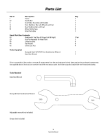
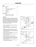
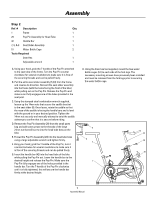
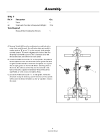
Assembly Step 1 Ref. # Description Qty 1 Frame 1 A Front Stabilizer Bar with Wheels and Feet 1 B Rear Stabilizer Bar with Feet 1 46 13mm Hex Bolt 4 44 Flat Washer 8 45 13mm Lock Nut 4 Tools Required Stamped Steel Combination Wrench 1 Adjustable wrench or 13mm Socket 1 ATTENTION Front The following steps utilize stainless steel hardware. Stainless steel hardware is susceptible to "cold welding", also known as 46 galling, if not handled properly. To reduce the chances for cold 44 welding, make sure you apply grease to the threads at the end of the stainless hex bolts #46. When tightening the 13mm lock nuts #45, turn them at a fairly low rotational speed. High rotational 1 speeds as well as lack of grease are common causes for cold welding of stainless steel hardware. A. Position the Front Stabilizer Bar (A) on the frame bracket as A shown in the illustration. 44 B. Make sure the adjustable feet are on the bottom and the 45 transport wheels are facing up and toward the front of the bike. C. Attach Front Stabilizer Bar (A) to Frame (1) using two hex bolts (46), four washers (44), and two lock nuts (45). Tighten hardware firmly but do not over tighten as deformation of the Rear stabilizer tube may occur D. At this time make sure that the adjustable feet with lock nuts 46 are screwed fully into the stabilizer. E. Position the Rear Stabilizer Bar (B) on the frame bracket as 44 shown in the illustration. F. Make sure the adjustable feet are on the bottom. G. Attach Rear Stabilizer Bar (B) to Frame (1) using two hex 1 bolts (46), four washers (44), and two lock nuts (45). Tighten hardware firmly but do not over tighten as deformation of the stabilizer tube may occur H. At this time make sure that the adjustable feet with lock nuts B 44 are screwed fully into the stabilizer. 45 6 Assembly Manual
-
 1
1 -
 2
2 -
 3
3 -
 4
4 -
 5
5 -
 6
6 -
 7
7 -
 8
8 -
 9
9 -
 10
10 -
 11
11 -
 12
12
 |
 |
