Seagate ST2000DM001 Barracuda SATA Product Manual - Page 31
Serial ATA (SATA) Interface, 4.1 Hot-Plug compatibility
 |
View all Seagate ST2000DM001 manuals
Add to My Manuals
Save this manual to your list of manuals |
Page 31 highlights
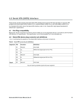
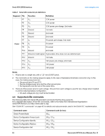
4.0 Serial ATA (SATA) Interface These drives use the industry-standard Serial ATA interface that supports FIS data transfers. It supports ATA programmed input/output (PIO) modes 0 to 4; multiword DMA modes 0 to 2, and Ultra DMA modes 0 to 6. For detailed information about the Serial ATA interface, refer to the "Serial ATA: High Speed Serialized AT Attachment" specification. 4.1 Hot-Plug compatibility Barracuda drives incorporate connectors which enable you to hot plug these drives in accordance with the Serial ATA Revision 2.5 specification. This specification can be downloaded from www.serialata.org. 4.2 Serial ATA device plug connector pin definitions Table 8 summarizes the signals on the Serial ATA interface and power connectors. Table 8 Serial ATA connector pin definitions Segment Pin Function Definition S1 Ground 2nd mate S2 A+ Differential signal pair A from Phy S3 A- S4 Ground 2nd mate S5 B- Differential signal pair B from Phy S6 B+ Signal S7 Ground 2nd mate Key and spacing separate signal and power segments Barracuda SATA Product Manual, Rev. B 31
-
 1
1 -
2
-
3
-
4
-
5
-
6
-
7
-
8
-
9
-
10
-
11
-
12
-
13
-
14
-
15
-
16
-
17
-
18
-
19
-
20
-
21
-
22
-
23
-
24
-
25
-
 26
26 -
 27
27 -
 28
28 -
 29
29 -
 30
30 -
 31
31 -
 32
32 -
 33
33 -
 34
34 -
 35
35 -
 36
36 -
37
-
38
-
39
-
40
-
41
-
42
-
43
-
44
-
45
-
46
-
47
-
48
 |
 |