Seagate ST336607LC ST3146807LC Model Product Manual PDF - Page 83
Cheetah 10K.6 SCSI Product Manual, Rev. D, Notes., Drive activity LED, Spindle status, Command
 |
UPC - 740617072488
View all Seagate ST336607LC manuals
Add to My Manuals
Save this manual to your list of manuals |
Page 83 highlights
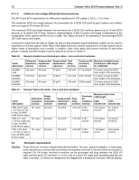
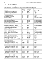
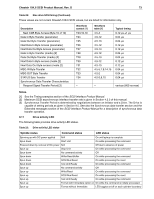
Cheetah 10K.6 SCSI Product Manual, Rev. D 73 Table 22: Disc drive SCSI timing (Continued) These values are not current Cheetah 10K.6 SCSI values, but are listed for information only. Description Next CDB Byte Access (Byte 10 of 10) Data In Byte Transfer (parameter) Data Out Byte Transfer (parameter) Next Data In Byte Access (parameter) Next Data Out Byte Access (parameter) Data In Byte Transfer (media) [2] Data Out Byte Transfer (media) [2] Next Data In Byte access (media [2] Next Data Out Byte access (media [2] MSG IN Byte Transfer MSG OUT Byte Transfer STATUS Byte Transfer Synchronous Data Transfer Characteristics: Request Signal Transfer Period [3] Waveform symbol [1] T23.10.10 T24 T25 T26 T27 T28 T29 T30 T31 T32 T33 T34 - Waveform table [1] 4.5-4 4.5-12 4.5-13 4.5-12 4.5-13 4.5-12 4.5-13 4.5-12 4.5-13 4.5-5,7,8,14,15 4.5-2 4.5-5,8,15 Typical timing 0.12 µs ±1 µs 0.04 µs 0.04 µs 0.12 µs 0.12 µs 0.04 µs 0.04 µs 0.12 µs 0.12 µs 0.04 µs 0.04 µs 0.04 µs - various (800 ns max) Notes. [1] See the Timing examples section of the SCSI Interface Product Manual. [2] Maximum SCSI asynchronous interface transfer rate is given in Section 4.2.3 of this manual. [3] Synchronous Transfer Period is determined by negotiations between an Initiator and a Drive. The Drive is capable of setting periods as given in Section 9.5. See also the Synchronous data transfer section and the Extended messages section of the SCSI Interface Product Manual for a description of synchronous data transfer operation. 9.11 Drive activity LED The following table provides drive activity LED status. Table 23: Drive activity LED status Spindle status Command status LED status Spinning up with DC power applied N/A On until spinup is complete Spun down Start Unit On while processing the command Powered down by removal of DC power N/A Off due to absence of power Spun up Stop Unit On while processing the command Spun down No command activity Off Spun down Write/Read Buffer On while processing the command Spun down SCSI Bus Reset On while processing the reset Spun down Test Unit Ready On while processing the command Spun up No command activity Off Spun up Write/Read On while processing the command Spun up SCSI Bus Reset On while processing the reset Spun up Test Unit Ready On while processing the command Spun up Format with Immediate option on On while the command is initially processed Spun up Format without Immediate LED toggles on/off on each cylinder boundary
-
 1
1 -
2
-
3
-
4
-
5
-
6
-
7
-
8
-
9
-
10
-
11
-
12
-
13
-
14
-
15
-
16
-
17
-
18
-
19
-
20
-
21
-
22
-
23
-
24
-
25
-
26
-
27
-
28
-
29
-
30
-
31
-
32
-
33
-
34
-
35
-
36
-
37
-
38
-
39
-
40
-
41
-
42
-
43
-
44
-
45
-
46
-
47
-
48
-
49
-
50
-
51
-
52
-
53
-
54
-
55
-
56
-
57
-
58
-
59
-
60
-
61
-
62
-
63
-
64
-
65
-
66
-
67
-
68
-
69
-
70
-
71
-
72
-
73
-
74
-
75
-
76
-
77
-
 78
78 -
 79
79 -
 80
80 -
 81
81 -
 82
82 -
 83
83 -
 84
84 -
 85
85 -
 86
86 -
 87
87 -
 88
88 -
89
-
90
-
91
-
92
-
93
-
94
-
95
-
96
 |
 |
