Seagate ST3500312CS Pipeline HD Series SATA Product Manual - Page 27
Drive mounting
 |
UPC - 715663213659
View all Seagate ST3500312CS manuals
Add to My Manuals
Save this manual to your list of manuals |
Page 27 highlights
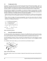
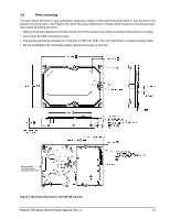
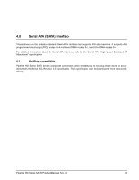
3.4 Drive mounting You can mount the drive in any orientation using four screws in the side-mounting holes or four screws in the bottom-mounting holes. See Figure 4 for drive mounting dimensions. Follow these important mounting precautions when mounting the drive: • Allow a minimum clearance of 0.030 inches (0.76 mm) around the entire perimeter of the drive for cooling. • Use only 6-32 UNC mounting screws. • The screws should be inserted no more than 0.150 inch (3.81 mm) into the bottom or side mounting holes. • Do not overtighten the mounting screws (maximum torque: 6 inch-lb). Recommended case temperature measurement location Figure 4. Mounting dimensions (for 500 GB models) Pipeline HD Series SATA Product Manual, Rev. C 21
-
 1
1 -
2
-
3
-
4
-
5
-
6
-
7
-
8
-
9
-
10
-
11
-
12
-
13
-
14
-
15
-
16
-
17
-
18
-
19
-
20
-
21
-
 22
22 -
 23
23 -
 24
24 -
 25
25 -
 26
26 -
 27
27 -
 28
28 -
 29
29 -
 30
30 -
 31
31 -
 32
32 -
33
-
34
-
35
-
36
-
37
-
38
-
39
-
40
-
41
-
42
-
43
-
44
-
45
-
46
 |
 |
Pipeline HD Series SATA Product Manual, Rev. C
21
3.4
Drive mounting
You can mount the drive in any orientation using four screws in the side-mounting holes or four screws in the
bottom-mounting holes. See Figure 4 for drive mounting dimensions. Follow these important mounting precau-
tions when mounting the drive:
•
Allow a minimum clearance of 0.030 inches (0.76 mm) around the entire perimeter of the drive for cooling.
•
Use only 6-32 UNC mounting screws.
•
The screws should be inserted no more than 0.150 inch (3.81 mm) into the bottom or side mounting holes.
•
Do not overtighten the mounting screws (maximum torque: 6 inch-lb).
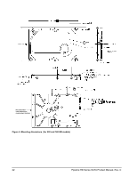
Figure 4. Mounting dimensions
(for 500 GB models)
Recommended
case temperature
measurement location