Seagate ST98823AS Momentus 5400.2 SATA Product Manual - Page 25
Drive mounting
 |
UPC - 000000098823
View all Seagate ST98823AS manuals
Add to My Manuals
Save this manual to your list of manuals |
Page 25 highlights
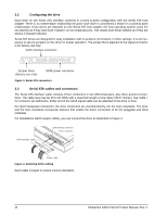
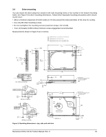
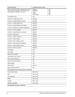
3.4 Drive mounting You can mount the drive using four screws in the side-mounting holes or four screws in the bottom-mounting holes. See Figure 5 for drive mounting dimensions. Follow these important mounting precautions when mounting the drive: • Allow a minimum clearance of 0.030 inches (0.76 mm) around the entire perimeter of the drive for cooling. • Use only M3 UNC mounting screws. • Do not overtighten the mounting screws (maximum torque: 4.0 inch-lb). • Four (4) threads (0.080 inches) minimum screw engagement recommended. Measurements shown in Figure 5 are in inches. C OF CONN. DATUM B C OF DRIVE ( .189 ) 2 2 .399 .157 2 1 DIMENSIONS PER EIA-720 OR SFF 8201 SPECIFICATION. 2 DIMENSIONS PER SFF 8212 OR SFF 8223. 3 DRIVE LENGTH W/ PATA IS 3.945±.057 (WORST CASE). DRIVE LENGTH W/ SATA IS 3.957±.062 (WORST CASE). 3.945 ± .010 (BASE) 1 2.750 ±.010 (BASE) ( .490 ) .217 ±.050 .217 ±.050 ( .673 ) SATA ( .020 ) SECTION B-B (SATA) .039 B C D 2 .152 .399 2 DETAIL A (PATA) B .039 B C D .016 C PATA .374 ±.008 -D- 2X .118 BOTH SIDES 1 BASE .551 1 3 3.567 1 BASE .551 1 3.567 (BASE) 1 B 2 .012 .370 2 DETAIL A (SATA) DETAIL A Figure 5. Mounting dimensions-top, side and end view 2X M3 X 0.5-6H MOUNTING HOLES; BOTH SIDES .12 MIN FULL THREAD 0.148 ±.010 X 90 1 4X M3 X 0.5-6H MOUNTING HOLES; BOTH SIDES .10 MIN FULL THREAD 0.148 ±.010 X 90 1 1 2.430 -B.160 1 -C- Momentus 5400.2 SATA Product Manual, Rev. C 19
-
 1
1 -
2
-
3
-
4
-
5
-
6
-
7
-
8
-
9
-
10
-
11
-
12
-
13
-
14
-
15
-
16
-
17
-
18
-
19
-
 20
20 -
 21
21 -
 22
22 -
 23
23 -
 24
24 -
 25
25 -
 26
26 -
 27
27 -
 28
28 -
 29
29 -
 30
30 -
31
-
32
-
33
-
34
-
35
-
36
-
37
-
38
-
39
-
40
-
41
-
42
-
43
-
44
 |
 |
