Seagate SV35 SV35.3 Series SATA Product Manual - Page 34
Serial ATA device plug connector pin definitions
 |
UPC - 000068216948
View all Seagate SV35 manuals
Add to My Manuals
Save this manual to your list of manuals |
Page 34 highlights
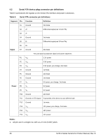
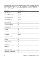
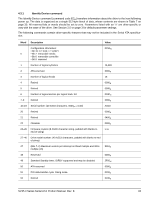
4.2 Serial ATA device plug connector pin definitions Table 6 summarizes the signals on the Serial ATA interface and power connectors. Table 6: Serial ATA connector pin definitions Segment Pin Function Definition S1 Ground S2 A+ S3 A- 2nd mate Differential signal pair A from Phy S4 Ground S5 BS6 B+ 2nd mate Differential signal pair B from Phy Signal S7 Ground 2nd mate Key and spacing separate signal and power segments P1 V33 P2 V33 P3 V33 P4 Ground 3.3V power 3.3V power 3.3V power, pre-charge, 2nd mate 1st mate P5 Ground P6 Ground P7 V5 Power P8 V5 P9 V5 P10 Ground 2nd mate 2nd mate 5V power, pre-charge, 2nd mate 5V power 5V power 2nd mate P11 Ground or LED signal If grounded, drive does not use deferred spin P12 Ground 1st mate. P13 V12 P14 V12 P15 V12 12V power, pre-charge, 2nd mate 12V power 12V power Notes: 1. All pins are in a single row, with a 1.27 mm (0.050") pitch. 28 SV35.3 Series Serial ATA Product Manual, Rev. B
-
 1
1 -
2
-
3
-
4
-
5
-
6
-
7
-
8
-
9
-
10
-
11
-
12
-
13
-
14
-
15
-
16
-
17
-
18
-
19
-
20
-
21
-
22
-
23
-
24
-
25
-
26
-
27
-
28
-
 29
29 -
 30
30 -
 31
31 -
 32
32 -
 33
33 -
 34
34 -
 35
35 -
 36
36 -
 37
37 -
 38
38 -
 39
39 -
40
-
41
-
42
-
43
-
44
-
45
-
46
-
47
-
48
-
49
-
50
-
51
-
52
-
53
-
54
 |
 |
