Sennheiser ASA 3000 Instructions for Use - Page 5
Connection diagram - asa
 |
View all Sennheiser ASA 3000 manuals
Add to My Manuals
Save this manual to your list of manuals |
Page 5 highlights
Connection diagram The below connection diagram shows the connections for an 8- or 16-channel system. ANT B ANT A Antenna booster e.g. AB 1036 Input B ASA 3000 Mains Antenna booster e.g. AB 1036 Input A 1 : 8 1 : 8 ANT B POWER ANT A 8 7 6 5 4 3 2 1 12 345678 EM 3000 1 B A EM 3000 2 B A EM 3000 8 B A 5
-
 1
1 -
 2
2 -
 3
3 -
 4
4 -
 5
5 -
 6
6 -
 7
7 -
 8
8 -
 9
9 -
 10
10 -
 11
11 -
12
-
13
 |
 |

5
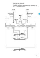
Connection diagram
The below connection diagram shows the connections for
an 8- or 16-channel system.
ASA 3000
ANT A
ANT B
Input B
ANT B
ANT A
Mains
Antenna booster
e.g. AB 1036
Antenna booster
e.g. AB 1036
Input A
POWER
B
A
B
A
B
A
1 : 8
1 : 8
1
2
3
4
5
6
7
8
8
7
6
5
4
3
2
1
EM 3000
EM 3000
EM 3000
1
2
8