Sennheiser ASP 1 Instructions for Use - Page 3
Antenna splitter, Instructions for use - asp 1
 |
View all Sennheiser ASP 1 manuals
Add to My Manuals
Save this manual to your list of manuals |
Page 3 highlights
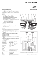
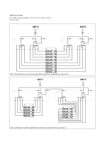
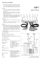
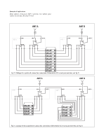
Instructions for use Passive RF antenna splitter for routing antenna signals to several receivers in a multi-channel system. Incorporates DC distribution for distributing the supply voltage to head amplifiers and up to four EM 100/300/500 receivers. ASP 1 Antenna splitter Features • 2 x 1-to-4 diversity splitter. Can be linked to form a single 1-to-8 splitter (ie: use two ASP 1 for an eight way diversity split). • DC distribution for supplying up to four EM 100/300/500 ቢ ባ receivers in addition to supplying up to two antenna head amplifiers. • Half-width 19", 1U high. By using the GA 1 rack mount adaptor the antenna splitter can be 19" rack mounted with: AM 1 antenna mount, ASP 1 antenna splitter, or EM 100/300/500 receiver. ቤብ ቦቧ ቨ Areas of application • Small to medium RF installations (fixed or mobile). • Permanent installations in small theatres, conference centres and similar venues. Connections ቢ DC input for NT 1 mains unit. The DC power is distributed to the four DC outputs ባ for powering up to four EM 100/ 300/500 receivers and is also available at the antenna inputs ቤ and ቨ for powering AB 1 antenna head amplifiers. Please note that the splitter is passive and DC power is not required for powering the splitter itself. ባ Four DC outputs for powering up to four EM 100/300/500 receivers. ቤ Antenna input B. ብ Four antenna outputs (B leg). ቦ Four antenna outputs (A leg). ቧ RF output A (link to antenna input B ቤ to make a 1-to-8 splitter). ቨ Antenna input A. Technical data Antenna splitter Frequency range Attenuation Dimensions Weight Supply voltage 2 x 1-to-4 passive (or 1 x 1-to-8, with link cable) 500-870 MHz approx. 9 dB IN B ©OUT B (4x) approx. 14 dB IN A © OUT A (4x) approx. 5 dB IN A © OUT A 212 x 38 x 145 mm (half-width 19", 1U high) approx. 800 g 10.5-16 V DC Accessories NT 1 NT 1-120 NT 1-UK GZL 1019-A1/A5/A10 AB 1 GA 1 AM 1 A 1031-U Mains power supply for powering up to four EM 100/300/500 receivers and two antenna boosters BNC antenna cable, 1 m, 5 m, 10 m Antenna booster (+10 dB) 19" rack adaptor Antenna mount (for connecting antennæ to front of rack) UHF passive antenna Dia. 1: Connections for a 4-channel system Subject to alterations. Errors and omissions excepted.
-
 1
1 -
 2
2 -
 3
3 -
 4
4 -
 5
5 -
 6
6 -
 7
7 -
 8
8 -
 9
9 -
10
-
11
-
12
 |
 |
