Sennheiser MKH 416 The MKH Story - Page 4
The Mkh Story - microphone
 |
View all Sennheiser MKH 416 manuals
Add to My Manuals
Save this manual to your list of manuals |
Page 4 highlights
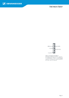
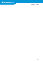
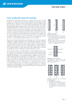
The MKH Story New non-linearity analysis A new challenge for microphone development arose at the beginning of the 1980s when digital recording found its way into the studios, and the LP was, over time, replaced by the CD. Now the music connoisseur, for the first time, could hear the filigrees of sound in the same way that the recording engineer could. But now any imperfections in the microphones, which were formerly concealed by the noise and distortion of the tape and the vinyl record, were now detectable by anyone with decent equipment. At that time Sennheiser made investigations on the sources of the tonal differences between studio microphones for optimising a new line of studio microphones. Not only the frequency responses and directional characteristics of established studio microphones were reviewed but their non-linear distortions were also analysed. At that time distortion measurements on microphones were regarded as problematic because sound sources with sufficiently low distortion were not available. Therefore the specified distortion exclusively concerned the microphone amplifier. Capsule distortion was not included. Sennheiser eliminated these difficulties by measuring the difference-frequency distortion instead of the more common harmonic distortion (THD). Two sounds of equal pressure (104 dB SPL) were applied simultaneously and separately via two loudspeakers to the microphone under test. The frequencies differed by 80 Hz. The distortion component generated by the microphone at the difference frequency 80 Hz (difference tone) was filtered out and measured. The distortion of the loudspeakers did not affect the test results because each loudspeaker produced only a single tone, and the harmonic distortions (THD) of the loudspeakers were far beyond the pass-band of the filter. The twin-tone signal was swept from 200 Hz to 20 kHz with an 80 Hz frequency offset. Contrary to THD measurements, the difference-frequency method enables measurements in the whole upper audio frequency range as the difference-frequency component is kept inside the audio frequency domain. The measurement results revealed very individual distortion characteristics of the various microphones. The distortions were low at low frequencies but increased remarkably at higher frequencies. The onset frequency was lower for large capsules and higher for small ones. The distortion increases almost linearly with the sound pressure. As the sound pressure level of the test tones was more than 20 dB below the overload level of the microphones, at least ten times higher distortion can be expected near the overload limit. Sine generator f1 = 200-20000 f1, 2f1, 3f1 etc. Sine generator f2 = 280-20080 f2, 2f2, 3f2 etc. f2-f1 = 80 Hz = const. 80 Hz Band-pass filter f2-f1 1. f1, f2 2. 2f1, 2f2, f2-f1, f1+f2 3. 3f1, 3f2 2f1-f2, 2f2-f1, 2f1+f2, 2f2+f1 etc. Difference frequency test set-up The microphone under test is simultaneously exposed to two tones of 104 dB SPL via two loudspeakers. The distortion component at f2-f1 is selected by a narrow band-filter and measured. Difference frequency distortion of studio condenser microphones (cardioids) The blue curve shows the improvement yielded by the push-pull capsule design of the MKH 40 compared with other top-quality studio condenser microphones Page 4
-
 1
1 -
 2
2 -
 3
3 -
 4
4 -
 5
5 -
 6
6 -
 7
7 -
 8
8 -
 9
9 -
 10
10
 |
 |
