Sharp 21SFX10L Service Manual
Sharp 21SFX10L Manual
 |
View all Sharp 21SFX10L manuals
Add to My Manuals
Save this manual to your list of manuals |
Sharp 21SFX10L manual content summary:
- Sharp 21SFX10L | Service Manual - Page 1
...2-1 INSTALLATION AND SERVICE INSTRUCTIONS 3-1 SERVICE MODE ...4-1 ADJUSTMENT METHOD ...5-1 WAVEFORMS ...6-1 CHASSIS LAYOUT ...7-1 BLOCK DIAGRAM ...8-1 DESCRIPTION OF SCHEMATIC DIAGRAM ...9-1 SCHEMATIC DIAGRAMS ...10-1 PRINTED WIRING BOARD ASSEMBLIES ...11-1 Parts Guide ELECTRICAL SPECIFICATIONS - Sharp 21SFX10L | Service Manual - Page 2
all service personnel are aware of the procedures and instructions covering X-radiation. The only potential source of X-ray in current solid state TV there is no possibility of an X-radiation problem. Every time a color chassis is serviced, the brightness should be tested while monitoring the - Sharp 21SFX10L | Service Manual - Page 3
Replacement parts which have these special safety characteristics are identified in this manual; electrical components having such features are identified by " " and shaded factory recommended replacement parts shown in this service manual, may create shock, fire, X-radiation or other hazards. 1 - 2 - Sharp 21SFX10L | Service Manual - Page 4
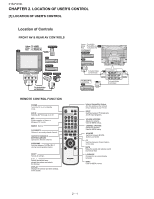
set. INPUT Switches between TV broadcasts and AV input programs. VOLUME UP/DOWN Adjusts the volume. Used for MENU setup. CHANNEL UP/DOWN Selects the channel. Used for MENU setup. AV MODE Switches between MOVIE, MUSIC and NEWS. CC Switches between Closed Caption service type. MUTE Mutes the sound and - Sharp 21SFX10L | Service Manual - Page 5
-iFecXet 1M0aLnual 3. INSTALLATION AND SERVICE INSTRUCTIONS 21S-FX10L Note: INSTALLATION AND SERVICE INSTRUCTIONS (1) When performing any adjustments to resistor controls and transformers use non-metallic screwdrivers or TV alignment tools. (2) Before performing adjustments, the TV set must be on - Sharp 21SFX10L | Service Manual - Page 6
mode, the following user data are set to default value and stored as last memory. PICTURE䋯TINT䋯COLOR䋯BRIGHT䋯SHARP䋯COLOR TEMP. BASS䋯TREBLE䋯BALANCE䋯MTS䋯FAO䋯SPEAKER䋯ENERGY SAVE 6䋮During Service mode, OSD display for ON/OFF is toggled via [CH CALL] key. 䊶At display OFF condition, if changing adjustment - Sharp 21SFX10L | Service Manual - Page 7
Adjustment Mode Items Data Service Mode Function Range Default Data V01 SUB-CON CONTRAST 0~127 127 V02 SUB-TINT TINT 0~127 64 V03 SUB-COL COLOR 0~127 64 V04 SUB- - Sharp 21SFX10L | Service Manual - Page 8
21S-FX10L AUTO ADJUSTMENT H-VCO 1. When there is H-VCO auto adjustment key input at item H-VCO, auto adjustment will be implemented. 2. H-FREE (1chip) is set to 1. 3. H-OUT (1chip) is set by intelligent monitor output. 4. IM input becomes TIM input. 5. H-VCO (1chip) data is changed so that the - Sharp 21SFX10L | Service Manual - Page 9
Setting Mode Items Data Service Mode Function F01 ABCL-Gain ABCL-G F02 SHP-AV-PRE F12 E-SAVE CONTRAST(OFFSET) F13 FAO-VOL A-ATT F14 VIF-G VIF-GAIN F15 YDL-TV Y-DELAY F16 YDL-TV-P Y-DELAY F17 YDL-TV-N3 Y-DELAY F18 YDL-AV Y-DELAY F19 YDL-AV-P Y-DELAY F20 YDL-AV-N3 - Sharp 21SFX10L | Service Manual - Page 10
YUV OFFSET BRIGHT (OFFSET) -63~+63 0 F65 TRAP TRAP-FINE 0~3 2 F66 TRAP-P TRAP-FINE 0~3 2 F67 TRAP-N3 TRAP-FINE 0~3 2 F68 AFC1-Gain-TV AFC1-G 0~3 0 F69 AFC1-Gain-AV AFC1-G 0~3 3 F70 AFC1-Gain-YUV AFC1-G 0~3 3 F71 OM-DET OM-Det 0/1 0 F72 BS-Gain 0/1 0 F73 - Sharp 21SFX10L | Service Manual - Page 11
COLOUR SETTING- MUSIC -30~+30 F119 COL MOVIE COLOUR SETTING- MOVIE -30~+30 F120 SHARP NEWS SHARPNESS SETTING- NEWS -30~+30 F121 SHARP MUSIC SHARPNESS SETTING- MUSIC -30~+30 F122 SHARP MOVIE SHARPNESS SETTING- MOVIE -30~+30 F123 SURR NEWS SURROUND SETTING- NEWS 0(OFF)/1(ON) F124 - Sharp 21SFX10L | Service Manual - Page 12
0/1 1 F151 BOW/ANGLE-ON/OFF BOW/ANGLE 0(OFF)/1(ON) 1 F152 SHP-NR-OFFSET VIDEO TONE -15~0 0 F153 V-FREE60 V-FREE60 0/1 1 F154 TAKEOFF TV TAKE-OFF 0/1 0 F155 STRAP OFFSET S-TRAP ADJ -16~+16 0 F156 RGB MUTE TIME 0~8 0 F157 H-BLK LEFT H-BLK LEFT 0~7 0 F158 H-BLK RIGHT - Sharp 21SFX10L | Service Manual - Page 13
F138 F139 F141 F143 F144 F145 F146 F156 F158 SERVICE ITEMS SUB-SHP-PRE SUB-SHP-OVER SUB-COLOR- N3 TINT-AV COL-AV R-R R-B B-R B-B GAMMA SL-TV AFC2 VD-TV VD-AV VD-YUV OSD POS-H OSD POS-V50 OSD CONT NEWS CONT MUSIC COL NEWS COL MOVIE SHARP NEWS SHARP MOVIE TREBLE NEWS TREBLE MOVIE BASS NEWS BASS - Sharp 21SFX10L | Service Manual - Page 14
21S-FX10L ADJ ITEM: OPTION SET UP (3RD STAGE SERVICE DATA) SERVICE ITEMS O01 LNA TUNER O02 FAO O03 PON-CH O04 ANTENNA BOOSTER O05 AV 1 O06 AV2 O07 MTS O08 COMPONENT O09 TONE-CTRL O10 AUTO- - Sharp 21SFX10L | Service Manual - Page 15
the oscilloscope to JA402 (Tuner's AGC Terminal) as shown in (I2C BUS CONTROL) figure 3-1. + OSCILLOSCOPE (AUTO & MANUAL ADJ) JA402 0.1V - + BIAS BOX TV SET - Bias Box : about 4.5V Fig. 3-1 (3) Call V09 in service mode. Adjust the V09 bus data to obtain the Tuner output pin drop 0.1V below - Sharp 21SFX10L | Service Manual - Page 16
V10 bus data until the overscan become 10 ± 2.5 %. Caution 1: Pls aging TV more than 10 minutes before adjustment 3 V-LINEARITY (1) Receive US4 CH LION HEAD Signal (NTSC 60 Hz). (I2C BUS CONTROL) (2) Choose the service data V29. (3 )Already preset. (Adjust this unless the linearity is achieved - Sharp 21SFX10L | Service Manual - Page 17
(3) Set V43 to 32 21S-FX10L WAVEFORM OR OTHERS 11 ANGLE ADJ (1) Receive CrossHatch Pattern Signal (NTSC 60 Hz). (I2C BUS CONTROL) (2) Choose the service data V41 (3) Adjust the 2nd vertical line from the end of the crosshatch pattern line is straight (4) Make sure both left / right of 2nd - Sharp 21SFX10L | Service Manual - Page 18
c) V15 : 127 d) V16 : 127 e) V17 : 127 f) V18 : 64 g) V19 : 64 (2) Receive the window pattern or US4 CH LION HEAD Signal (NTSC 60 Hz) (3) Go to service mode, get in Y-mute by R/C and set V23 to "1" (4) Adjust the Screen so that cut-off line appear in low bright, then judge that whether - Sharp 21SFX10L | Service Manual - Page 19
the oscilloscope to JA410 or TP853 BLUE-OUT (I2C BUS CONTROL) Range : 500mV/Div (AC) (Use Probe 10:1) Sweep time : 10μsec/Div (3) Select the service data V02 . On Y-mute using the R/C. (4) Adjust the V02 (Sub tint) data to obtain the waveform as shown in Figure 1.1 (B-Amp Base (TP853) must be - Sharp 21SFX10L | Service Manual - Page 20
(1.2 Vp-p ± 0.3Vp-p). 2 VIDEO AND AUDIO (1) Using the INPUT key on the remote controller, make sure that the modes change in order of INPUT CHECK TV, COMPONENT, INPUT1,INPUT2 & TV again and the video & audio output are according to the input terminal for each mode. (2) Video cross-talk INPUT to - Sharp 21SFX10L | Service Manual - Page 21
and select TINT. (3) Press Volume Up/Down key to check TINT, UP for GREEN direction and DOWN for RED direction whether is OK or not. 5 SHARPNESS Key (1) Receive "US 4 CH LION HEAD Signal (NTSC 60 Hz)" signal. (2) Press to Menu mode, then select Picture Mode and set to select - Sharp 21SFX10L | Service Manual - Page 22
to normal setting. (Normal setting of selected AV mode) MOVIE MODE PICTURE COLOUR BRIGHTNESS TINT SHARP PICTURE NR COLOR TEMP MUSIC MODE 60 PICTURE 60 +6 COLOUR 0 0 BRIGHTNESS 0 0 TINT 0 +6 SHARP 0 OFF PICTURE NR OFF Mid COLOR TEMP Mid NEWS MODE PICTURE 50 COLOUR -6 BRIGHTNESS - Sharp 21SFX10L | Service Manual - Page 23
(2) Make sure M.P IN feature is set to ON (3) Plug in stereo cable in M.P IN terminal (4) 'MP IN' OSD will appear at bottom right corner TV screen, RF channel sound will be switched to M.P IN sound. (5) Check the sound is normal 16 NOISE MUTE (1) Receive mono-tone signal. CHECKING (2) Turn - Sharp 21SFX10L | Service Manual - Page 24
21S-FX10L CHAPTER T2SME1VeaSrrvk-iFecXet 1M0aLnual 6. WAVEFORMS (1)1.94 Vp-p (2)4.54 Vp-p (3)3.68 Vp-p (4)4.22 Vp-p Horiz. Rate (5)3.14 Vp-p Horiz. Rate (6)4.92 Vp-p Horiz. Rate (7)5.88 Vp-p Horiz. Rate (8)1.35 Vp-p Horiz. Rate (9)2.81 Vp-p Vert. Rate (10)37.80 Vp-p Horiz. Rate (11)1076 - Sharp 21SFX10L | Service Manual - Page 25
CHAPTER T2SME1VeaSrrvk-iFecXet 1M0aLnual 7. CHASSIS LAYOUT 21S-FX10L H 21S-FX10L G F E D C B A 1 2 3 4 5 6 7 8 9 10 7 - 1 - Sharp 21SFX10L | Service Manual - Page 26
21S-FX10L CHAPTER T2SME1VeaSrrvk-iFecXet 1M0aLnual 8. BLOCK DIAGRAM H G F E D C B A 1 2 3 4 5 6 7 8 9 10 8 - 1 - Sharp 21SFX10L | Service Manual - Page 27
21S-FX10L 10 11 12 13 14 15 16 17 18 19 8 - 2 - Sharp 21SFX10L | Service Manual - Page 28
21S-FX10L H 21S-FX10L G F E D C B A 1 2 3 4 5 6 7 8 9 10 8 - 3 - Sharp 21SFX10L | Service Manual - Page 29
CHAPTER T2SME1VeaSrrvk-iFecXet 1M0aLnual 9. DESCRIPTION OF SCHEMATIC DIAGRAM 21S-FX10L DESCRIPTION OF SCHEMATIC DIAGRAM NOTES: 1. The unit of resistance "ohm" is omitted. (K=kΩ=1000Ω, M=MΩ) 2. All resistors are 1/16 watt, unless otherwise noted. 3. All capacitors are μF, unless otherwise noted. - Sharp 21SFX10L | Service Manual - Page 30
21S-FX10L CHAPTER T2SME1VeaSrrvk-iFecXet 1M0aLnual 10. SCHEMATIC DIAGRAM H G F E D C B A 1 2 3 4 5 6 7 8 9 10 10 - 1 - Sharp 21SFX10L | Service Manual - Page 31
21S-FX10L 10 11 12 13 14 15 16 10 - 2 17 18 19 - Sharp 21SFX10L | Service Manual - Page 32
21S-FX10L H G F E D C B A 1 2 3 4 5 6 7 8 9 10 10 - 3 - Sharp 21SFX10L | Service Manual - Page 33
CHAPTER T2SME1VeaSrrvk-iFecXet 1M0aLnual 11. PRINTED WIRING BOARD ASSEMBLIES 21S-FX10L H G F E D C B A 1 2 PWB-A : MAIN UNIT ( Wiring Side ) 3 4 5 6 7 8 11 - 1 9 10 - Sharp 21SFX10L | Service Manual - Page 34
21S-FX10L H G F E D C B A 1 PWB-A : MAIN UNIT ( Chip Parts Side ) 2 3 4 5 6 7 8 11 - 2 9 10 - Sharp 21SFX10L | Service Manual - Page 35
21S-FX10L H G F E D C B A 1 2 PWB-B : CRT UNIT (Wring Side ) 3 4 5 6 7 8 11 - 3 9 10 - Sharp 21SFX10L | Service Manual - Page 36
21S-FX10L H G F E D C B PWB-B : CRT UNIT ( Chip Parts Side ) A 1 2 3 4 5 6 7 8 9 10 11 - 4 - Sharp 21SFX10L | Service Manual - Page 37
PartsGuide 21S-FX10L PARTS GUIDE No. XXXNXOX.S2X9X12X52X1SXFXX1X0L XXXXXXXX MODEL 21S-FX10L CONTENTS [1] PICTURE TUBE [2] PRINTED WIRING BOARD ASSEMBLIES ( NOT REPLACEMENT document has been published to be used for after sales service only. The contents are subject to change without notice. - Sharp 21SFX10L | Service Manual - Page 38
21S-FX10L NO. PARTS CODE PRICE NEW PART RANK MARK RANK DESCRIPTION [1] PICTURE TUBE ! VB51QGT420X2E R SEMI-ITC Picture Tube ! RCILGA172WJZZ R Degaussing Coil QEARCA052WJZZ AG R Ground-Part [2] PRINTED WIRING BOARD ASSEMBLIES ( NOT REPLACEMENT ITEM ) DUNTKE907WEA0 - DUNTKE908WEA0 - - Sharp 21SFX10L | Service Manual - Page 39
NO. PARTS CODE [3] MAIN UNIT L203 L204 L602 L603 L605 L701 L801 L802 L803 L804 L805 L807 L808 L3001 SF201 T602 T603 T702 C202 C203 C204 C206 C207 C208 C209 C210 C211 C212 C301 C302 C303 C304 C305 C306 C308 C309 C310 C314 C370 C371 C372 C390 C391 C393 C394 C395 C451 C501 C505 C508 C509 C511 C513 - Sharp 21SFX10L | Service Manual - Page 40
21S-FX10L NO. PARTS CODE [3] MAIN UNIT C755 C756 C757 C758 C760 C761 C767 C784 C803 C804 C805 C806 C807 C811 C812 C813 C814 C815 C816 C818 C819 C824 C825 C826 C828 C830 C831 C833 C834 C836 C838 C839 C840 C841 C842 C843 C844 C845 C1001 C1002 C1003 C1004 C1007 C1008 C1013 C1016 C1017 C1018 C1019 - Sharp 21SFX10L | Service Manual - Page 41
NO. PARTS CODE [3] MAIN UNIT C3017 C3018 C3019 C3020 C3021 C3022 C3023 C3024 C3025 C3026 C3027 C3028 C3051 C3052 C3061 C3062 RJ2 RJ15 RJ16 RJ18 RJ19 RJ21 RJ22 RJ23 RJ24 RJ25 RJ26 RJ31 RJ32 RJ34 RJ37 RJ41 RJ44 RJ45 RJ46 RJ47 RJ48 RJ52 RJ62 RJ78 R201 R202 R205 R206 R207 R208 R209 R217 R220 R301 - Sharp 21SFX10L | Service Manual - Page 42
21S-FX10L NO. PARTS CODE [3] MAIN UNIT R507 R513 R514 R515 R520 R523 R524 R526 R601 R602 R603 R605 R607 R608 R609 R611 R612 R614 R615 R616 R617 R618 R621 R622 R637 R638 R639 R642 R643 R644 R662 R671 R672 R673 R674 R675 R676 R677 R678 R679 R702 R704 R710 R711 R713 R720 R721 R725 R726 R727 R750 - Sharp 21SFX10L | Service Manual - Page 43
NO. PARTS CODE [3] MAIN UNIT R832 VRS-CY1JF222JY R833 VRS-CY1JF222JY R834 VRS-CY1JF222JY R835 VRS-CY1JF181JY R836 VRS-CY1JF181JY R837 VRS-CY1JF181JY R838 VRS-CY1JF472JY R840 VRS-CY1JF332JY R841 VRS-CY1JF333JY R1001 VRD-RA2BE101JY R1002 VRS-CY1JF103JY R1003 VRS-CY1JF102JY R1004 VRD- - Sharp 21SFX10L | Service Manual - Page 44
R 560 1/8W Carbon R Plug 4Pin (H) R Plug 5Pin (K) R Socket , 12Pin R AC Cord R SPEAKER R SP WIRE (+--+) R H-WIRE R K-WIRE RRMCGA571WJSA TINS-D896WJZZ UBATUA017WJZZ R Infrared Remote Control Unit R Operation Manual R Battery DESCRIPTION 8 - Sharp 21SFX10L | Service Manual - Page 45
[6] CABINET PARTS FRONT VIEW 1-2 1-1 1 21S-FX10L 1-6 1-7 1-10 1-11 1-3 1-4 1-5 1-8 1-9 1-12 2-1 2 REAR VIEW NO. PARTS CODE [6] CABINET PARTS 1 1-1 1-2 1-3 1-4 1-5 1-6 1-7 1-8 1-9 1-10 1-11 1-12 2 2-1 CCABAB974WEV9 Not Available Not Available Not Available Not Available JBTN-A766WJSA - Sharp 21SFX10L | Service Manual - Page 46
PARTS ( NOT REPLACEMENT ITEM 0 MODEL: 21S-FX10L PACKING OF THE SET 5 SPAKP0097PEZZ * WRAPPING SHEET 6 SSAKA0001PEZZ * SACK FOR O/M Operation Manual MP-IN Cable Batteries Infra Red Remote control unit 4 SPAKXC191WJZZ *PACKING FOAM 7 TLABKA008WJZZ * WH LABEL 3 SPAKCE517WJZZ * PACKING CASE FINALLY - Sharp 21SFX10L | Service Manual - Page 47
„INDEX PARTS CODE [ C ] CCABAB974WEV9 CCABBB377WEV1 [ D ] DUNTKE907WEA0 DUNTKE908WEA0 [ G ] GCOVAC579WJSA GDORFA243WJSA [ H ] HDECQA848WJSA HINDPC875WJSA [ J ] JBTN-A766WJSA [ L ] LHLDW1104PEZZ " LHLDW1105PEZZ " [ M ] MSPRC0005PEFW [ N ] Not Available " " " " [ P ] PKAI-0002PE00 PRDARA119WJFW - Sharp 21SFX10L | Service Manual - Page 48
21S-FX10L PARTS CODE VCEA0A1AW107M+ VCEA0A1AW108M+ VCEA0A1AW477M+ VCEA0A1CW106M+ VCEA0A1CW107M+ VCEA0A1CW226M+ " " " " VCEA0A1CW227M+ VCEA0A1CW336M+ " VCEA0A1CW476M+ " " " " VCEA0A1CW477M+ " VCEA0A1EW226M+ VCEA0A1EW228M+ " VCEA0A1EW476M+ VCEA0A1EW477M+ VCEA0A1HW104M+ VCEA0A1HW105M+ " " " " " - Sharp 21SFX10L | Service Manual - Page 49
PARTS CODE VHEZJ33C+++1EY VHEZJ5R1A++1EY VHEZJ5R1B++1EY " VHEZJ5R6C++1EY VHEZJ8R2B++1EY VHILA42102+-1 VHILA72703V-1Y VHILA78041+-1 VHIM24C08W6-1Y VHIMM1501XN-1Y " " " VHIPQ05RDA1-1 VHISE125N++-F VHISTRW6553-1 VP-CF100K0000Y " VP-CF220K0000Y VP-DF100K0000Y VP-MK820K0000+ VP-XF2R2K0000Y VRD-RA2BE101JY - Sharp 21SFX10L | Service Manual - Page 50
21S-FX10L PARTS CODE " " " VRS-CY1JF105JY VRS-CY1JF121JY " " VRS-CY1JF122JY VRS-CY1JF123JY VRS-CY1JF124JY VRS-CY1JF151JY VRS-CY1JF152JY " VRS-CY1JF181JY " " VRS-CY1JF183JY " " " " VRS-CY1JF221JY " " " VRS-CY1JF222JY " " " VRS-CY1JF223JY " VRS-CY1JF271JY " " VRS-CY1JF272JY " " " VRS-CY1JF274JY VRS- - Sharp 21SFX10L | Service Manual - Page 51
a retrieval system, or transmitted in any form or by any means, electronic, mechanical, photocopying, recording, or otherwise, without prior written permission of the Information Design :SREC Production :SREC CHS.SMM - 1 SHARP MANUFACTURING CORPORATION (M) SDN. BHD PQA DEPARTMENT Batu Pahat, Johor,
-
 1
1 -
 2
2 -
 3
3 -
 4
4 -
 5
5 -
 6
6 -
 7
7 -
8
-
9
-
10
-
11
-
12
-
13
-
14
-
15
-
16
-
17
-
18
-
19
-
20
-
21
-
22
-
23
-
24
-
25
-
26
-
27
-
28
-
29
-
30
-
31
-
32
-
33
-
34
-
35
-
36
-
37
-
38
-
39
-
40
-
41
-
42
-
43
-
44
-
45
-
46
-
47
-
48
-
49
-
50
-
51
 |
 |
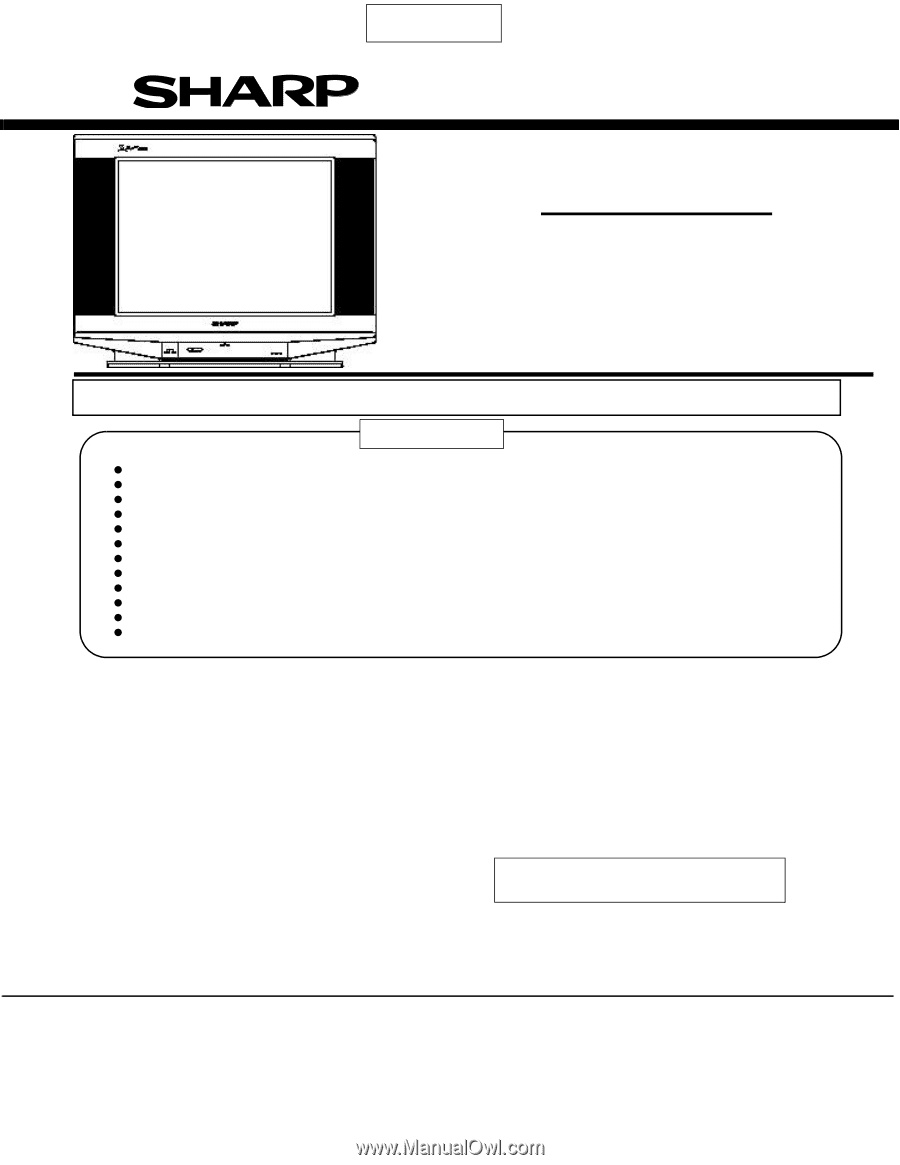
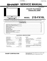
SERVICE MANUAL
COLOUR TELEVISION
Chassis No. GA6
21S-FX10L
In the interests of user safety (Required by safety regulations in some countries) the set should be restored to its original
condition and only parts indentical to those specified should be used.
S2912521SFX10L
MODEL
ELECTRICAL SPECIFICATIONS
Chassis No. GA8S
CONTENTS
IMPORTANT SERVICE SAFETY PRECAUTION
...................................................................................................
1-1
Page
LOCATION OF USER’S CONTROL
......................................................................................................................
2-1
INSTALLATION AND SERVICE INSTRUCTIONS
.................................................................................................
3-1
SERVICE MODE
.....................................................................................................................................................
4-1
ADJUSTMENT METHOD
........................................................................................................................................
5-1
WAVEFORMS
.........................................................................................................................................................
6-1
CHASSIS LAYOUT
.................................................................................................................................................
7-1
BLOCK DIAGRAM
..................................................................................................................................................
8-1
DESCRIPTION OF SCHEMATIC DIAGRAM
..........................................................................................................
9-1
SCHEMATIC DIAGRAMS
......................................................................................................................................
10-1
PRINTED WIRING BOARD ASSEMBLIES
...........................................................................................................
11-1
Parts Guide
POWER INPUT
............................
AC 110-220 V, 50/60 Hz
POWER RATING
.....................................................
92W
PICTURE SIZE
.............................
1,239 cm
2
(192sq inch)
CONVERGENCE
.............................................
Magnetic
SWEEP DEFLECTION
..................................
.. Magnetic
FOCUS
.........................................................
Electrostatic
INTERMEDIATE FREQUENCIES
Picture IF Carrier Frequency
......................
45.75 MHz
Sound IF Carrier Frequency
......................
41.25 MHz
Color Sub-Carrier Frequency
......................
42.17 MHz
(Nominal)
AUDIO POWER
OUTPUT RATING...
......................
3.0 W(RMS) x 4pcs
SPEAKER
SIZE
........................................................
9 x 5cm, 4pcs
VOICE COIL IMPEDANCE
.................
32 ohm at 400 Hz
ANTENNA INPUT IMPEDANCE
VHF/UHF
........................................
75 ohm Unbalanced
TUNING RANGES
VHF-Channels
.................................................
2 thru 13
UHF-Channels
................................................
14 thru 69
CATV Channels
.............................................
1 thru 125
(EIA, Channel Plan U.S.A.)
Specifications are subject to change without
prior notice.
SHARP CORPORATION
This document has been published to be used for after
sales service only.
The contents are subject to change without notice.
21S-FX10L
1st Edition