Sharp AR-RB1 Service Manual
Sharp AR-RB1 Manual
 |
View all Sharp AR-RB1 manuals
Add to My Manuals
Save this manual to your list of manuals |
Sharp AR-RB1 manual content summary:
- Sharp AR-RB1 | Service Manual - Page 1
SERVICE MANUAL CODE: 00ZARRB1//A1E DIGITAL FULL COLOR COPIER/PRINTER/ MULTIFUNCTIONAL SYSTEM OPTION DUPLEX BYPASS/INVERTER UNIT MODEL AR-RB1 CONTENTS [1] SPECIFICATIONS 1-1 [2] UNPACKING AND INSTALLATION 1-1 [3] INTERIOR CONSTRUCTION 3-1 [4] DESCRIPTION OF OPERATION 4-1 [5] DISASSEMBLY, - Sharp AR-RB1 | Service Manual - Page 2
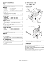
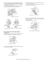
• Start installation after checking that the DATA indicator on the operation panel is neither lit nor blinking. • For installation of AR-RB1, an optional stand (AR-D17/AR-D18/ARD19) must have been installed. • Ensure that the connecting plate located on the front side of the optional stand and - Sharp AR-RB1 | Service Manual - Page 3
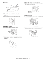
of the two paper output section covers on the left side of the main unit to remove them. Transport guide holder: 2 pcs. 1. Turn off the main switch of the main unit. 1) Turn the main switch remove the actuator. Paper input section cover Exit actuator AR-RB1 UNPACKING AND INSTALLATION 2 - 2 - Sharp AR-RB1 | Service Manual - Page 4
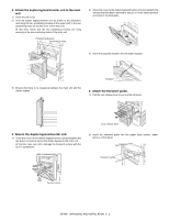
between the main unit and the duplex bypass. Actuator 6. Attach the transport guide. 1) Pull the lock release lever to pull out the left cover. the transport guide into the paper input section (upper groove) of the stand. Transport guide Transport surface AR-RB1 UNPACKING AND INSTALLATION 2 - - Sharp AR-RB1 | Service Manual - Page 5
guide holders Front side Rear side Notch Transport guide Notch Transport guide Transport guide holder Notches Transport guide on the rear cabinet, and attach the cover with the screw. Installation of AR-RB1 is now complete. Screw Pawls Power supply cover Relay harness Power supply cover - Sharp AR-RB1 | Service Manual - Page 6
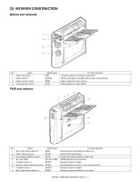
and controller Detects transport of paper Detects presence of paper in the reverse section Detects transport of paper Detects open/closed status of lower door AR-RB1 INTERIOR CONSTRUCTION 3 - 1 - Sharp AR-RB1 | Service Manual - Page 7
ADU. Transports paper to ADU. Applies a pressure to the upper transport roller to transport paper. Applies a pressure to the upper reverse roller to transport paper. AR-RB1 INTERIOR CONSTRUCTION 3 - 2 - Sharp AR-RB1 | Service Manual - Page 8
operations include straight delivery, reverse tray delivery, reverse finisher delivery, and ADU delivery (when AR-D19 is installed) operations. [Sensor and solenoid operation] BIM (paper in-motor) changes the detects the passing paper, it turns off the motor. AR-RB1 DESCRIPTION OF OPERATION 4 - 1 - Sharp AR-RB1 | Service Manual - Page 9
Envelope OHP (priority: quality) OHP (priority: speed) Copier process speed 58.5 117 58.5 117 RB1 tray delivery speed 58.5 117 120 160 Unit: mm/s Sensor input, motor output, solenoid output of paper-out) Process speed BGSOL (Gate solenoid) Delivery speed AR-RB1 DESCRIPTION OF OPERATION 4 - 2 - Sharp AR-RB1 | Service Manual - Page 10
edge of the paper reaches a point 13mm from the copier POD off, the transport speed in RB1 is accelerated. Trailing edge of paper reaches point 13mm from POD off When the trailing edge of paper-out) BGSOL (Gate solenoid) High speed Low speed High speed AR-RB1 DESCRIPTION OF OPERATION 4 - 3 - Sharp AR-RB1 | Service Manual - Page 11
trailing edge of the paper reaches a point 13mm from the copier POD off, the transport speed in RB1 is accelerated. Trailing edge of paper reaches point 13mm from POD off When the trailing edge of -out) High speed Low speed High speed High speed High speed AR-RB1 DESCRIPTION OF OPERATION 4 - 4 - Sharp AR-RB1 | Service Manual - Page 12
trailing edge of the paper reaches a point 13mm from the copier POD off, the transport speed in RB1 is accelerated. Trailing edge of paper reaches point 13mm from POD off When the trailing edge of the by the same conditions as for letter-size or less. AR-RB1 DESCRIPTION OF OPERATION 4 - 5 - Sharp AR-RB1 | Service Manual - Page 13
) (Direction of paper-out) BTM (Lower reverse motor) (Direction of paper-in) (Direction of paper-out) BGSOL (Gate solenoid) High speed High speed High speed AR-RB1 DESCRIPTION OF OPERATION 4 - 6 - Sharp AR-RB1 | Service Manual - Page 14
❍ ❍ ❍ ❍ ❍ ❍ ❍ ❍ ❍ ❍ ❍ ❍ ❍ ❍ Drive unit 3 Transport paper guides 4 Gears 5 Belts ❍ ❍ ❍ ❍ ❍ ❍ ❍ ❍ ❍ ✕ ✕ ✕ ✕ ✕ (designated rollers/torque limiter parts: 100K or 2 years. 2 2 1 2 1 2 1 1 2 2 4 4 3 3 7 6 6 5 6 5 AR-RB1 DISASSEMBLY, ASSEMBLY AND MAINTENANCE 5 - 1 - Sharp AR-RB1 | Service Manual - Page 15
❍ ❍ ❍ ❍ ❍ ❍ ❍ ❍ ❍ ❍ ❍ ❍ ❍ ❍ ❍ ❍ ❍ 3 Transport paper guides ❍ ❍ ❍ ❍ ❍ ❍ ❍ ❍ ❍ ❏ : Relocate Remarks (1) All transport rollers a. Copier 1) Detach the E-rings, gears and bearings, and take out (B) the paper input roller. B AR-RB1 DISASSEMBLY, ASSEMBLY AND MAINTENANCE 5 - 2 - Sharp AR-RB1 | Service Manual - Page 16
the E-rings, belt, pulley, pin and bearings. 3) Remove (A) the upper transport roller. B A 3) Remove the E-rings, belt, pulley, pin and bearings. Take out (C) the delivery roller. C A AR-RB1 DISASSEMBLY, ASSEMBLY AND MAINTENANCE 5 - 3 - Sharp AR-RB1 | Service Manual - Page 17
Remove the screws, and take out (C) the paper delivery cabinet unit. (3) Transport paper guides C B A B. Drive section ✕ : Check (for cleaning, replacement or adjustment as Gears a. Copier 1) Remove the rear casing. 2) Remove the front gears. AR-RB1 DISASSEMBLY, ASSEMBLY AND MAINTENANCE 5 - 4 - Sharp AR-RB1 | Service Manual - Page 18
1) Open the upper open/closed unit, remove the E-ring and bearing, and take out (A) the gate unit. 2) Remove the screw, and remove (B) the upper cabinet. B A AR-RB1 DISASSEMBLY, ASSEMBLY AND MAINTENANCE 5 - 5 - Sharp AR-RB1 | Service Manual - Page 19
, remove the screws, and remove (A) the paper input motor. A (4) Bypass drive PWB 1) Detach the connector, remove the screws, and take out (A) the bypass drive PWB. A AR-RB1 DISASSEMBLY, ASSEMBLY AND MAINTENANCE 5 - 6 - Sharp AR-RB1 | Service Manual - Page 20
AR-RB1 ELECTRICAL SECTION 6 - 1 [6] ELECTRICAL SECTION (1) Actual wiring chart AR-D17/18/19 XADRP-40V 1 N.C. 1 2 /BPOD 2 3 /BPFD 3 4 /BPPD1 4 5 /BPPD2 5 6 / 7 1 GND 8 9 3 +5V 2 /BPOD BPOD 1 GND CN-H B6B-PH-K-R BRM/B 1 +24V 2 BRMB 3 BRMA 4 +24V 5 BRM/A 6 BRM AR-RB1 - Sharp AR-RB1 | Service Manual - Page 21
fan motor +24V Paper input motor +24V Turnover motor BTM BPOD BPFD BPPD1 BPPD2 BPRD BDD1 BDD2 BGSOL BFM BIM BRM AR-RB1 GND GND 4 Chopping circuit (MTD1361) Transistor Transistor 4 Chopping circuit (MTD1361) 6 Chopping circuit (MTD1361) +5V 6 +24V 4 /BPOD1 /BPFD1 /BPPD1 /BPPD2 /BPRD - Sharp AR-RB1 | Service Manual - Page 22
8 7 6 5 4 3 2 1 (4) Circuit diagram AR-RB1 ELECTRICAL SECTION 6 - 3 D +24V CNA-26 +24V CNA-27 +24V CNA-28 +5V CNA-29 CNA-30 CNA-31 CNA-32 GND GND /BYSET CP3 +5V - Sharp AR-RB1 | Service Manual - Page 23
AR-RB1 ELECTRICAL SECTION 6 - 4 (5) Layout of parts A. Parts side B. Solder side - Sharp AR-RB1 | Service Manual - Page 24
Memo - Sharp AR-RB1 | Service Manual - Page 25
UNIT MODEL AR-RB1 CONTENTS 1 Exteriors & Left door unit) 2 Upper Open/Shut unit) 3 Delivery paper unit & Upper transport section) 4 Lower transport section & Frame section) 5 Reverse base section) 6 配線部 (Wiring section) 7 Packing material & Accessories) I 索引 (Index) SHARP CORPORATION - Sharp AR-RB1 | Service Manual - Page 26
F F Other than this Parts Guide, please refer to documents Service Manual(including Circuit Diagram)of this model PRICE RANK Ex. Ja. AA DD AC DJ AG DS BD GJ AN EG AE DS AL EB AC DJ AC DJ BC GJ AR EQ AD DJ AC DJ AE DS AA DD AV FG AS EZ AF DS BH GX AC DJ NEW MARK N N N N - Sharp AR-RB1 | Service Manual - Page 27
2 Upper Open/Shut unit) 21 XEBSE40P10000 AA DD C 22 PBRSS0221FCZZ AT EZ N B 24 XEBSE30P10000 AA DD C 25 LBSHZ0303FCZZ AC DJ C 26 XRESP40-06000 AA DD C Screw(4×10) Discharge brush Screw(3×10) M bush(C) E-ring(E4) 1 Exteriors & Left door unit) M C) E 2 1 1 2 1 3 8 3 11 - Sharp AR-RB1 | Service Manual - Page 28
sensor fixing plate One way gear(18T) Sub roller D Transport sub shaft Transport sub spring Delivery cabinet Photo sensor(GP1A71L) Flange mylar RB1 Belt(60S2M150) Pulley(S2M40) Belt(40S3M309) Pulley 20P(S3M) Screw(4×6) Motor fixing plate lower Mini clamp Screw(3×6) ADU transport motor lower Spring - Sharp AR-RB1 | Service Manual - Page 29
ring(E5) Lower reverse roller Micro wire saddle Bearing(B-F6-63) Transport roller lower Spring pin(3×10) E-ring(E7) Bearing(B-F8-13) Flange mylar RB1 Spring pin Delivery roller Pulley 20P(S3M) Belt(60S2M186) Pulley(S2M40) Pulley(24P) Belt(40S3M204) Belt(40S3M225) Joint stay Frame earth plate spring - Sharp AR-RB1 | Service Manual - Page 30
20 21 18 6 配線部 (Wiring section) NO. PARTS CODE 1 DHAI-3398FCZZ 2 DHAI-3383FCZZ 3 DHAI-3379FCZZ 4 DHAI-3382FCZZ 5 DHAI-3381FCZZ PRICE RANK Ex. Ja. AE DS AR EQ BC GJ AU EZ AG DS NEW MARK N N N N N PART RANK C C C C C BY earth harness 2 BY delivery sensor harness BY interface harness BY reverse - Sharp AR-RB1 | Service Manual - Page 31
6 配線部 (Wiring section) 2 1 3 4 5 7 Packing material NO. PARTS CODE 1 MLEVP0879FCZZ 2 LHLDZ1543FCZZ 3 SSAKA0006UCZZ 4 PGIDW2006FCZZ 5 SPAKA6352FCZZ 6 0EUSAK0615P// 7 SPAKC6373FCZZ SPAKC6351FCZZ 8 SPAK-545ECCZZ 9 SPAKA6196FCZZ PRICE RANK Ex. Ja. AK DX AG DS AA DD BD GN AZ FQ AF DS BB - Sharp AR-RB1 | Service Manual - Page 32
FQ N C 5- 12 BP LP N E 6- 3 BC GJ N C 6- 5 AG DS N C 6- 4 AU EZ N C 6- 2 AR EQ N C 6- 1 AE DS N C 2- 4 BD GJ N D 3- 28 BG GT N D 1- 8 BC GD N D 1- FX N B AY FQ N B AX FG N B AU FG N C AU FG N C AW FG N C AW FG N C AR EQ N C AX FG N C 2- 22 AT EZ N B 2- 17 AS EZ N C 2- 19 BH GX N C 1- 21 - Sharp AR-RB1 | Service Manual - Page 33
PARTS CODE [0] 0EUGER0423N01 0EUHLD0309G// 0EULEV0402JW2 0EUSAK0615P// JAPAN ONLY ORDER CODE 572 281 1894 572 214 1585 572 248 1464 572 906 0124 PRICE R. NO. NEW P/R Ex. Ja. 3- 24 AN EG B 4- 9 AD DJ C 1- 14 AU EZ N C 7- 6 AF DS D PARTS CODE JAPAN ONLY ORDER CODE PRICE R. NO. NEW P/R - Sharp AR-RB1 | Service Manual - Page 34
Memo - Sharp AR-RB1 | Service Manual - Page 35
type ou d'un type équivalent recommandé par le constructeur. Mettre au rebut les batteries usagées conformément aux instructions du fabricant. (Swedish) VARNING Explosionsfara vid felaktigt batteribyte. Använd samma batterityp eller en ekvivalent typ som rekommenderas av apparattillverkaren - Sharp AR-RB1 | Service Manual - Page 36
Incorporated. NetWare is a registered trademark of Novell, Inc. All other trademarks and copyrights are the property of their respective owners. SHARP CORPORATION Digital Document System Group Products Quality Assurance Department Yamatokoriyama, Nara 639-1186, Japan 2003 January Printed in Japan
-
 1
1 -
 2
2 -
 3
3 -
 4
4 -
 5
5 -
 6
6 -
 7
7 -
8
-
9
-
10
-
11
-
12
-
13
-
14
-
15
-
16
-
17
-
18
-
19
-
20
-
21
-
22
-
23
-
24
-
25
-
26
-
27
-
28
-
29
-
30
-
31
-
32
-
33
-
34
-
35
-
36
 |
 |
SERVICE MANUAL
CODE: 00ZARRB1//A1E
DIGITAL FULL COLOR COPIER/PRINTER/
MULTIFUNCTIONAL SYSTEM OPTION
DUPLEX BYPASS/INVERTER UNIT
MODEL
AR-RB1
CONTENTS
[1]
SPECIFICATIONS . . . . . . . . . . . . . . . . . . . . . . . . . . . . . . . . . . . . . 1-1
[2]
UNPACKING AND INSTALLATION . . . . . . . . . . . . . . . . . . . . . . . . 1-1
[3]
INTERIOR CONSTRUCTION. . . . . . . . . . . . . . . . . . . . . . . . . . . . . 3-1
[4]
DESCRIPTION OF OPERATION . . . . . . . . . . . . . . . . . . . . . . . . . . 4-1
[5]
DISASSEMBLY, ASSEMBLY AND MAINTENANCE . . . . . . . . . . . 5-1
[6]
ELECTRICAL SECTION. . . . . . . . . . . . . . . . . . . . . . . . . . . . . . . . . 6-1
PARTS GUIDE
Parts marked with “
” are important for maintaining the safety of the set. Be sure to replace these parts with
specified ones for maintaining the safety and performance of the set.
SHARP CORPORATION
This document has been published to be used
for after sales service only.
The contents are subject to change without notice.