Sharp ER-A242 ER-A242 Operation Manual - Page 6
Parts And Their Functions
 |
View all Sharp ER-A242 manuals
Add to My Manuals
Save this manual to your list of manuals |
Page 6 highlights
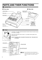
PARTS AND THEIR FUNCTIONS 1 External View Front view Operator display Printer cover Rear view Customer display (Pop-up type) Receipt paper Power cord Mode switch Drawer Drawer lock Keyboard RS-232C connector 2 Printer The printer is one station type thermal printer, therefore it does not require any type of ink ribbon or cartridge. Lift the rear of the printer cover to remove. To re-install, hook the pawls on the cabinet and close. Caution: The paper cutter is mounted on the printer cover. Be careful not to cut yourself. Take-up spool Print roller arm Print roller release rever Inner cover 4 Paper roll cradle Paper positioning guides Do not attempt to remove the paper roll with the print roller arm is locked. This may result in damage to the printer and print head.
-
 1
1 -
 2
2 -
 3
3 -
 4
4 -
 5
5 -
 6
6 -
 7
7 -
 8
8 -
 9
9 -
 10
10 -
 11
11 -
 12
12 -
13
-
14
-
15
-
16
-
17
-
18
-
19
-
20
-
21
-
22
-
23
-
24
-
25
-
26
-
27
-
28
-
29
-
30
-
31
-
32
-
33
-
34
-
35
-
36
-
37
-
38
-
39
-
40
-
41
-
42
-
43
-
44
-
45
-
46
-
47
-
48
-
49
-
50
-
51
-
52
-
53
-
54
-
55
-
56
-
57
-
58
-
59
-
60
-
61
-
62
-
63
-
64
-
65
-
66
-
67
-
68
-
69
-
70
-
71
-
72
 |
 |
