Sharp PN-L602B PN-L602B Quick Start Guide - Page 10
Specifications, Mounting Precautions For SHARP dealers and service engineers
 |
View all Sharp PN-L602B manuals
Add to My Manuals
Save this manual to your list of manuals |
Page 10 highlights
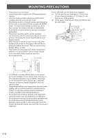
Specifications Model Power requirement Operating temperature * Operating humidity Power consumption (Maximum) Dimensions (excluding protrusions) Weight PN-L602B AC 100 V - 240 V, 2.0 A, 50/60 Hz 41°F to 95°F (5°C to 35°C) 20% to 80% (no condensation) 165 W [When PN-ZB01 (optional) is attached: 170 W] inch (mm) Approx. 56-11/16 (W) x 4 (D) x 33-11/16 (H) (1,440 x 101 x 855) lbs. (kg) Approx. 119.0 (54) [PN-ZB01 (optional): Approx. 1.102 (0.5)] * Temperature condition may change when using the monitor together with the optional equipments recommended by SHARP. In such cases, please check the temperature condition specified by the optional equipments. As a part of our policy of continuous improvement, SHARP reserves the right to make design and specification changes for product improvement without prior notice. The performance specification figures indicated are nominal values of production units. There may be some deviations from these values in individual units. Mounting Precautions (For SHARP dealers and service engineers) • When installing, removing or moving the monitor, ensure that this is carried out by at least 2 people. • Be sure to use a wall-mount bracket designed or designated for mounting the monitor. • This monitor is designed to be installed on a concrete wall or pillar. Reinforced work might be necessary for some materials such as plaster / thin plastic board / wood before starting installation. This monitor and bracket must be installed on a wall which can endure at least 4 times or more the weight of the monitor. Install by the most suitable method for the material and the structure. • To attach a VESA-compliant mounting bracket, use M6 screws that are 5/16 inch (8 mm) to 3/8 inch (10 mm) longer than the thickness of the mounting bracket. • After mounting, please carefully ensure the monitor is secure, and not able to come loose from the wall or mount. • Do not use any screw holes other than VESA holes for installation. nAttaching the Tray 1. Remove the cover from the back of the monitor. 3. Secure the tray. Insert the tray into the tray mounting fitting and secure with 2 M4 tray mounting screws (supplied). 2. Secure the tray mounting fitting. Secure using the screw removed in step 1 and 2 M5 tray mounting screws (supplied). Tray (supplied) M4 tray mounting screws (supplied) Cover (supplied) Bracket (supplied) E8 (2) (3) M5 tray mounting screws (supplied) (1) Tray mounting fitting Screw removed in step 1
-
 1
1 -
2
-
3
-
4
-
 5
5 -
 6
6 -
 7
7 -
 8
8 -
 9
9 -
 10
10 -
 11
11 -
 12
12 -
 13
13 -
 14
14 -
 15
15 -
16
-
17
-
18
-
19
-
20
-
21
-
22
-
23
-
24
-
25
-
26
-
27
-
28
 |
 |
