Sharp R-201FW Service Manual
Sharp R-201FW Manual
 |
View all Sharp R-201FW manuals
Add to My Manuals
Save this manual to your list of manuals |
Sharp R-201FW manual content summary:
- Sharp R-201FW | Service Manual - Page 1
ENERGY INSIDE FRONT COVER BEFORE SERVICING ...INSIDE FRONT COVER WARNING TO SERVICE PERSONNEL ...1 MICROWAVE MEASUREMENT PROCEDURE 2 FOREWORD AND WARNING ...3 PRODUCT SPECIFICATIONS ...4 GENERAL INFORMATION ...4 OPERATION ...6 TROUBLESHOOTING GUIDE ...9 TEST PROCEDURE ...10 TOUCH CONTROL PANEL - Sharp R-201FW | Service Manual - Page 2
to the owner. BEFORE SERVICING Before servicing an operative unit, perform a microwave emission check as per the Microwave Measurement Procedure outlined in this service manual. If microwave emissions level is in excess of the specified limit, contact SHARP ELECTRONICS CORPORATION immediately @1-800 - Sharp R-201FW | Service Manual - Page 3
Service Manual carefully and follow all instructions. Don't Touch ! Danger High Voltage Before Servicing use of an insulated screwdriver. Whenever troubleshooting is performed the power supply must door and set the power to HIGH and set the microwave timer for two (2) minutes. When the two minutes - Sharp R-201FW | Service Manual - Page 4
specified in its instruction booklet. Important: Survey instruments that comply with the requirement for instrumentation as prescribed by the performance standard for microwave ovens, 21 before any door movement. NOTE: After servicing, record data on service invoice and microwave leakage report. 2 - Sharp R-201FW | Service Manual - Page 5
SERVICE MANUAL MICROWAVE OVEN R-201FK/ R-201FW/ R-203FW/ R-205FW/ R-206FW FOREWORD This Manual has been prepared to provide Sharp Electronics Corp. Service Personnel with Operation and Service Information for the SHARP MICROWAVE OVENS, R-201FK, R-201FW, R-203FW, R205FW and R-206FW. It is recommended - Sharp R-201FW | Service Manual - Page 6
Clock (1:00 - 12:59) Timer (0 - 99 minutes 99 seconds) Microwave Power for Variable Cooking Repetition Rate; P-HI Full power throughout the cooking time , CFR, Title 21, Chapter 1, Subchapter J GENERAL INFORMATION GROUNDING INSTRUCTIONS This oven is equipped with a three prong grounding plug. It - Sharp R-201FW | Service Manual - Page 7
surfaces 6 Turntable motor shaft 7 Removable turntable support 7 1 Carefully place the turntable support in the center of the oven floor. 8 panel 13 Time display: 99 minutes, 99 seconds TOUCH CONTROL PANEL R-201FW R-203FW R-205FW R-206FW NOTE: R-201FK Some one-touch cooking features such - Sharp R-201FW | Service Manual - Page 8
transformer, oven lamp, etc. are turned off, and the generation of microwave energy is stopped. The oven will revert to the OFF condition. 6. Note: The ON/OFF time ratio does not correspond with the percentage of microwave power, because approx. 3 seconds are needed for heating of the magnetron - Sharp R-201FW | Service Manual - Page 9
SCHEMATIC NOTE: CONDITION OF OVEN 1. DOOR CLOSED 2. CLOCK APPEARS ON DISPLAY R-201FK/W R-203FW R-205FW R-206FW NOTE: " " indicates components with potentials above 250V. C/T FUSE TEMPERATURE FUSE (OVEN) N.O. COM. POWER TRANSFORMER (RY-1) (RY-2) A3 PRIMARY INTERLOCK RELAY 120V AC 60 Hz - Sharp R-201FW | Service Manual - Page 10
to prevent damage to the magnetron. If an over heated condition develops in the magnetron due to cooling fan failure, obstructed air guide, dirty or blocked air intake, etc., the C/T fuse will open. Under normal operation, the C/T fuse remains closed. However, when abnormally high temperatures - Sharp R-201FW | Service Manual - Page 11
with your hand or an uninsulated tool while the power supply is connected. When troubleshooting the microwave oven, it is helpful to follow the Sequence of Operation in performing the checks. Many of the possible causes of trouble will require that a specific test be performed. These tests are given - Sharp R-201FW | Service Manual - Page 12
FAN MOTOR TURNTABLE MOTOR CONTROL UNIT OR RELAY WRONG OPERATION LOW VOLTAGE DIRTY OVEN CAVITY KEY UNIT FOIL PATTERN ON PWB. EXPRESS DEFROST CONDITION PROBLEM Home fuse blows when power cord is plugged into wall receptacle. C/T fuse blows when power cord is plugged into wall receptacle. OFF - Sharp R-201FW | Service Manual - Page 13
the power supply cord after the outer case is installed. 9. Run the oven and check all functions. MICROWAVE OUTPUT POWER The following test procedure should be carried out with the microwave oven in a fully assembled condition (outer case fitted). HIGH VOLTAGES ARE PRESENT DURING THE COOK CYCLE - Sharp R-201FW | Service Manual - Page 14
operation of control unit. Check for restricted air flow through the vent holes of the oven cavity, especially the cooling fan and air guide. 5. Reconnect all leads removed from components during testing. 6. Reinstall the outer case (cabinet). 7. Reconnect the power supply cord after the outer case - Sharp R-201FW | Service Manual - Page 15
TEST PROCEDURES R-201FK/W R-203FW R-205FW R-206FW PROCEDURE LETTER COMPONENT TEST 8. Run the oven and check all functions. PRIMARY INTERLOCK SYSTEM TEST DOOR SENSING SWITCH 1. Disconnect the power supply cord, and then remove outer case. 2. Open the door and block it open. 3. Discharge high - Sharp R-201FW | Service Manual - Page 16
magnetron, especially the cooling fa air guide. CAUTION: IF THE C/T FUSE microwave ovens, proper maintenance cannot be performed with only a voltmeter and ohmmeter. In this service manual, the touch control panel assembly is divided into two units, Control Unit and Key Unit, and troubleshooting - Sharp R-201FW | Service Manual - Page 17
to light up. e) Wrong figure appears. f) A certain group of indicators do not light up. g) The figure of all digits flicker. 2-3 Other possible problems caused by defective control unit. a) Buzzer does not sound or continues to sound. b) Clock does not operate properly. c) Cooking is not possible - Sharp R-201FW | Service Manual - Page 18
by D.C. voltage Check voltage at the relay coil with a D.C. voltmeter during the microwave cooking operation. DC. voltage indicated Defective relay. DC. voltage not indicated Check diode it open. 3) Discharge high voltage capacitor. 4) Follow the troubleshooting guide given below for repair. 16 - Sharp R-201FW | Service Manual - Page 19
case (cabinet). 8) Reconnect the power supply cord after the outer case is installed. 9) Run the oven and check all functions. 2. Follow the troubleshooting guide given below, if indicator does not light up after above check and repairs are finished. 1) Disconnect the power supply cord and then - Sharp R-201FW | Service Manual - Page 20
R-201FK/W R-203FW R-205FW R-206FW TOUCH CONTROL PANEL ASSEMBLY OUTLINE OF TOUCH CONTROL PANEL The touch control section consists of the following units as shown in the touch control panel circuit. (1) Key Unit (2) Control Unit The principal functions of these units and their related signals are - Sharp R-201FW | Service Manual - Page 21
DESCRIPTION OF LSI R-201FK/W R-203FW R-205FW R-206FW The I/O signal of the LSI are detailed in the following table. Pin No. Signal 1 RESET 2 TEST 3 VSS 4 OCS3 5 6 7 8 9 10 11-13 OCS4 VD1 VDD AVDD AVREF AVSS P40-P42 14 P43 15 BZ 16 R00 17 R01 18 R02 19 R03 20 P20 21 P21 - Sharp R-201FW | Service Manual - Page 22
R-201FK/W R-203FW R-205FW R-206FW Pin No. 25 Signal K01 26 K02 27 K03 I/O Description IN Signal similar to K02. When either G9 line on key matrix is touched, a corresponding signal will be input into K01. IN Signal coming from touch key. When either G10 line on key matrix is touched, a - Sharp R-201FW | Service Manual - Page 23
the touch control panel with power supply of the oven : CAUTION: THE HIGH VOLTAGE TRANSFORMER OF THE MICROWAVE OVEN IS STILL LIVE DURING SERVICING AND PRESENTS A HAZARD . Therefore, before checking the performance of the touch control panel, 1) Disconnect the power supply cord and then remove - Sharp R-201FW | Service Manual - Page 24
the oven. to microwave energy. Please follow the instructions below before 1. 1. Without the RF gasket (Magnetron). 2. If the wave guide or oven cavity are not intact. 3. If the door is cavity. 3) Sharp edge: Bottom plate, Oven cavity, Waveguide flange, Chassis support and other metallic - Sharp R-201FW | Service Manual - Page 25
to free it from retaining clips on the cavity face plate. 6. Lift entire outer case from the unit. CAUTION: 1. DISCONNECT OVEN FROM POWER SUP- PLY BEFORE REMOVING OUTER CASE. 2. DISCHARGE THE HIGH VOLTAGE CA- R-201FK/W R-203FW R-205FW R-206FW PACITOR BEFORE TOUCHING ANY OVEN COMPONENTS OR WIRING. - Sharp R-201FW | Service Manual - Page 26
Figure C-2. Graphic Sheet and Membrane Switch Replacement TURNTABLE MOTOR REMOVAL Removal 1. Disconnect the power supply cord. 2. Remove the turntable and turntable support from the oven cavity. 3. Turn the oven over. 4. Remove the one (1) screw holding the turntable motor cover to the bottom - Sharp R-201FW | Service Manual - Page 27
with the two (2) screws. 2. Install the fan blade to the fan motor shaft according to the following procedure. 3. Hold the center of the bracket which supports the shaft of the fan motor on the flat table. 4. Apply the screw lock tight into the hole (for shaft) of the fan blade. 5. Install - Sharp R-201FW | Service Manual - Page 28
not head. bend or warp the slit choke (tabs on the door 14.Now, latch head and latch spring are free. panel assembly) to prevent microwave leakage. 15.Remove door screen from door frame. 8 Choke Cover 7 6 9 10 11 16.Now, door screen is free. RE-INSTALL 1. Re-install door screen to - Sharp R-201FW | Service Manual - Page 29
switch are operating properly. (Refer to chapter "Test Procedures".). (B) An approved microwave survey meter should be used to assure compliance with proper microwave radiation emission limitation standards. After any service, make sure of the following : 1. Door latch heads smoothly catch latch - Sharp R-201FW | Service Manual - Page 30
28 6 5 4 3 2 1 H H RY1 H N G G F F CONTROL PANEL 2 1 CN-B ORG RED RY2 PRIMARY INTERLOCK RELAY COM. ORG N.O. T1 1 CN-A 3 CN-A 1 ORG 2 3 WHT GRN GRN CN-B 2 GRY 1 GRN ORG BLK DOOR SENSING SWITCH COM N.O. GRY GRN TEMPERATURE FUSE (OVEN) MONITOR SWITCH RED N.C. COM GRY GRY - Sharp R-201FW | Service Manual - Page 31
A B C D E F G H 1 1 2 2 VRS1 10G471K (J1) D1-D4 1N4002 D1 D3 POWER UNIT C2 470µ/25v D4 T1 D2 + + - - d ab R4 910 1/2w AC(N) A3 c CN-A AC120V 60Hz OVEN LAMP RY1 TURNTABLE A1 MOTOR FAN MOTOR MICRO COM AC(H) NO B1 B2 DOOR CN-B SENSING SWITCH RY2 D21 D20 Q21 - Sharp R-201FW | Service Manual - Page 32
(J11) (J10) D3 D4 D1 C2 D E F G H 6 PARTS LIST Note: The parts marked "∆" may cause undue microwave exposure. The parts marked "*" are used in voltage more than 250V. REF. NO. 1- 1 1- 1 1- 2 1- 3 1- 3 * 1- 4 * 1- 4 * 1- 5 * 1- 5 * 1- 5 1- 6 1- 6 1- 6 ∆* 1- 7 ∆* 1- 7 1- 8 1- 9 1- 9 1-10 * 1-11 - Sharp R-201FW | Service Manual - Page 33
205FW][R-206FW] 1 Door screen [R-201FK][R-201FW] 1 Door screen [R-203FW][R-205FW][R-206FW] 1 Latch head 1 Spring 1 Sealer film 1 Choke cover 1 MISCELLANEOUS Turntable 1 Turntable support 1 Monitor caution 1 DHHS caution label 1 Instruction book 1 Main wire harness 1 SCREWS - Sharp R-201FW | Service Manual - Page 34
NUMBER 2. REF. NO. 3. PART NO. 4. DESCRIPTION Order Parts from the authorized SHARP parts Distributor for your area. Defective parts requiring return should be returned as indicated in the Service Policy. 1 2 3 4 5 6 A A CONTROL PANEL PARTS Before attaching Control unit to Control - Sharp R-201FW | Service Manual - Page 35
1 2 OVEN AND CABINET PARTS A 2-1 3 4 5 7-10 7-3 7-10 7-10 R-201FK/W R-203FW R-205FW R-206FW 6 A B B 7-3 C D E 4-5 F 4-8 6-1 G 6-2 H 4-9 1-10 7-7 6-3 7-11 1-8 7-9 7-10 4-3 7-9 7-10 7-2 6-4 1-7 4-4 1-6 7-6 C 1-2 4-12 7-10 D 7-8 4-11 1-3 4-9 7-5 E 7-10 1-11 7-2 F 4-1 7-4 - Sharp R-201FW | Service Manual - Page 36
4 DOOR PROTECTION SHEET SPADPA580WRE0 6-5 INSTRUCTION BOOK 6-1 TURNTABLE TRAY MICROWAVE OVEN 6-2 TURNRTABLE SUPPORT 5 6 TOP PAD ASSEMBLY A 201FW] SPAKCD732WREZ [R-201FK] FPAK-A420WRKZ [R-203FW] FPAK-A429WRKZ [R-205FW] SPAKCD730WREZ [R-206FW] H 3 4 5 6 COPYRIGHT © 2002 BY SHARP
-
 1
1 -
 2
2 -
 3
3 -
 4
4 -
 5
5 -
 6
6 -
 7
7 -
8
-
9
-
10
-
11
-
12
-
13
-
14
-
15
-
16
-
17
-
18
-
19
-
20
-
21
-
22
-
23
-
24
-
25
-
26
-
27
-
28
-
29
-
30
-
31
-
32
-
33
-
34
-
35
-
36
 |
 |
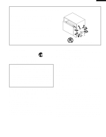
R-201FK/W
R-203FW
R-205FW
R-206FW
MICROWAVE OVEN
In the interest of user-safety the oven should be restored to its original
condition and only parts identical to those specified should be used.
WARNING TO SERVICE PERSONNEL: Microwave ovens con-
tain circuitry capable of producing very high voltage and
current, contact with following parts may result in a severe,
possibly fatal, electrical shock. (High Voltage Capacitor, High
Voltage Power Transformer, Magnetron, High Voltage Recti-
fier Assembly,
High Voltage Harness etc..)
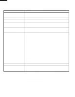
TABLE OF CONTENTS
Page
PRECAUTIONS TO BE OBSERVED BEFORE AND DURING SERVICING TO
AVOID POSSIBLE
EXPOSURE TO EXCESSIVE MICROWAVE ENERGY
...................
INSIDE FRONT COVER
BEFORE SERVICING
......................................................................................................
INSIDE FRONT COVER
WARNING TO SERVICE PERSONNEL
................................................................................................................
1
MICROWAVE MEASUREMENT PROCEDURE
...................................................................................................
2
FOREWORD AND WARNING
...............................................................................................................................
3
PRODUCT SPECIFICATIONS
..............................................................................................................................
4
GENERAL
INFORMATION
...................................................................................................................................
4
OPERATION
..........................................................................................................................................................
6
TROUBLESHOOTING GUIDE
..............................................................................................................................
9
TEST PROCEDURE
............................................................................................................................................
10
TOUCH CONTROL PANEL
.................................................................................................................................
18
COMPONENT REPLACEMENT AND ADJUSTMENT PROCEDURE
................................................................
22
PICTORIAL DIAGRAM
........................................................................................................................................
28
CONTROL PANEL CIRCUIT
...............................................................................................................................
29
PRINTED WIRING BOARD
.................................................................................................................................
30
PARTS LIST
........................................................................................................................................................
30
PACKING AND ACCESSORIES
.........................................................................................................................
34
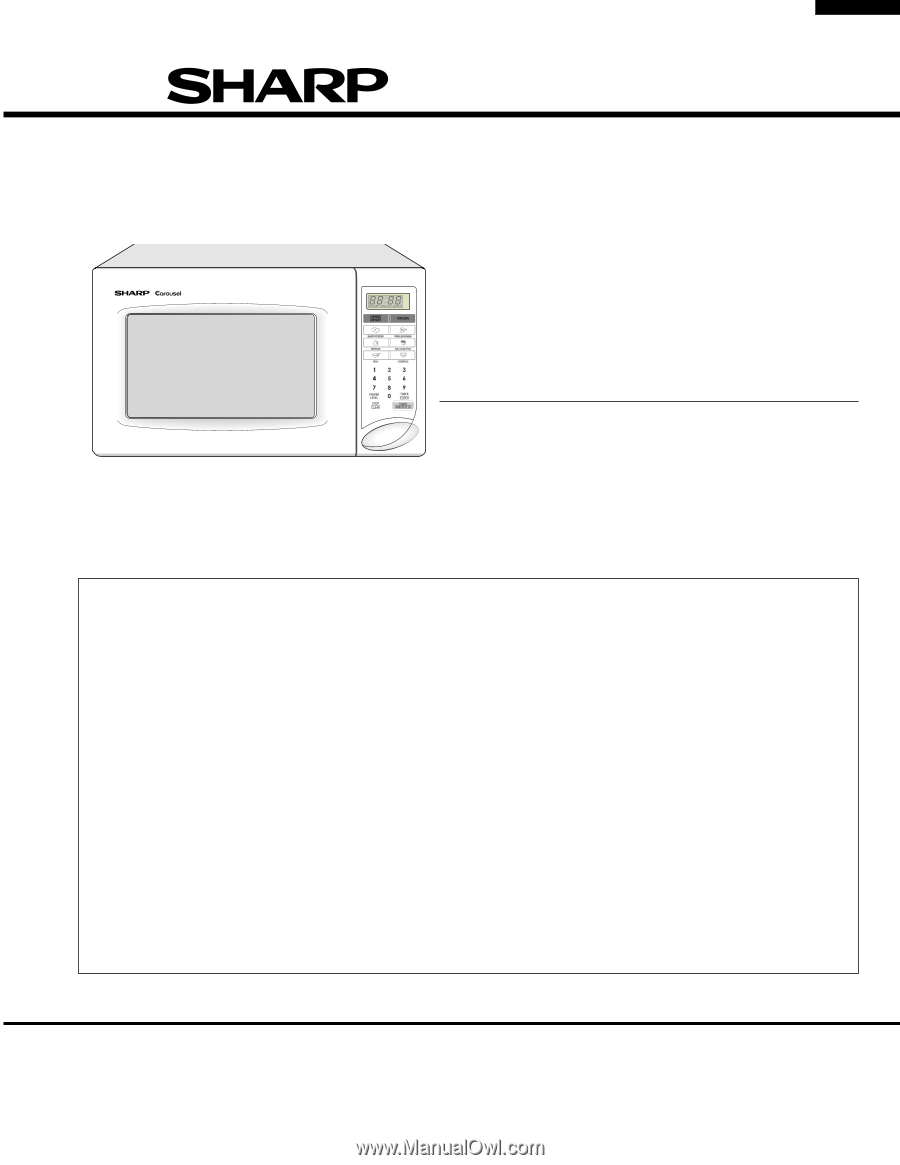
S1201R201FPW/
R-201FK/W
R-203FW
R-205FW
R-206FW
MODELS
SERVICE MANUAL
SHARP CORPORATION
This document has been published to be used for after
sales service only.
The contents are subject to change without notice.
R-206FW