Sharp R-230HW Service Manual
Sharp R-230HW Manual
 |
View all Sharp R-230HW manuals
Add to My Manuals
Save this manual to your list of manuals |
Sharp R-230HW manual content summary:
- Sharp R-230HW | Service Manual - Page 1
R-220HW R-230HW SERVICE MANUAL S2303R220HPW/ MICROWAVE OVEN R-230HW MODELS R-203HW R-220HW R-230HW In the interest of user-safety the oven should be restored to its original condition and only parts identical to those specified should be used. WARNING TO SERVICE PERSONNEL: Microwave ovens contain - Sharp R-230HW | Service Manual - Page 2
on each oven prior to release to the owner. BEFORE SERVICING Before servicing an operative unit, perform a microwave emission check as per the Microwave Measurement Procedure outlined in this service manual. If microwave emissions level is in excess of the specified limit, contact SHARP ELECTRONICS - Sharp R-230HW | Service Manual - Page 3
230HW WARNING TO SERVICE PERSONNEL Microwave ovens contain circuitry capable of producing very high voltage and current, contact with following parts etc.. Read the Service Manual carefully and follow all instructions. Don't Touch ! Danger High Voltage Before Servicing 1. Disconnect the power - Sharp R-230HW | Service Manual - Page 4
R-203HW R-220HW R-230HW MICROWAVE MEASUREMENT PROCEDURE A. Requirements: 1) Microwave leakage limit (Power density limit): The power density of microwave radiation emitted by a microwave oven should not exceed 1mW/cm2 at any point 5cm or more from the external surface of the oven, measured prior - Sharp R-230HW | Service Manual - Page 5
SERVICE MANUAL MICROWAVE OVEN R-203HW/ R-220HW/ R-230HW FOREWORD This Manual has been prepared to provide Sharp Electronics Corp. Service Personnel with Operation and Service Information for the SHARP MICROWAVE OVENS, R-203HW, R-220HW and R-230HW. It is recommended that service personnel carefully - Sharp R-230HW | Service Manual - Page 6
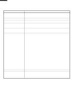
230HW ITEM Power Requirements Power Consumption Power Output Case Dimensions Cooking Cavity Dimensions (0.8 Cubic feet) Control Complement Oven (0 - 99 minutes 99 seconds) Microwave Power for Variable Cooking Repetition Rate; GENERAL INFORMATION GROUNDING INSTRUCTIONS This oven is equipped with a - Sharp R-230HW | Service Manual - Page 7
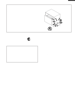
220HW R-230HW Electrical Requirements 6 Turntable motor shaft 7 Removable turntable support Carefully place the turntable support in the center 7 1 of the oven floor. R-220HW R230HW NOTE: Some one-touch cooking features such as "MINUTE PLUS" are disabled after three minutes when the oven is not - Sharp R-230HW | Service Manual - Page 8
microwave energy is stopped. The oven will revert to the OFF condition. 6. When the door is opened during a cook cycle, monitor switch, door sensing switch, secondary interlock switch and primary interlock relay are activated with the following results. The circuits to the oven lamp, turntable motor - Sharp R-230HW | Service Manual - Page 9
INTERLOCK RELAY 120V AC 60 Hz GRN CONTROL UNIT A1 B2 B1 OL OVEN LAMP SECONDARY INTERLOCK SWITCH TTM FM DOOR SENSING SWITCH TURNTABLE MOTOR FAN MOTOR MONITOR SWITCH Figure O-1. Oven Schematic-Off Condition CAPACITOR 0.82µF AC2100V RECTIFIER MAGNETRON SCHEMATIC NOTE: CONDITION OF - Sharp R-230HW | Service Manual - Page 10
220HW R-230HW DESCRIPTION switch contact fail to TURNTABLE MOTOR The turntable motor rotates the turntable located on the bottom of the oven cavity, so that the food develops in the magnetron due to cooling fan failure, obstructed air guide, dirty or blocked air intake, etc., the C/T fuse will - Sharp R-230HW | Service Manual - Page 11
GUIDE R-203HW R-220HW R-230HW Never touch any part in the circuit with your hand or an uninsulated tool while the power supply is connected. When troubleshooting the microwave oven, it is helpful to follow the Sequence of Operation in performing the checks. Many of the possible causes of trouble - Sharp R-230HW | Service Manual - Page 12
SECONDARY INTERLOCK SWITCH MONITOR SWITCH C/T FUSE OVEN LAMP OR SOCKET COOLING FAN MOTOR TURNTABLE MOTOR CONTROL UNIT OR RELAY WRONG OPERATION LOW VOLTAGE DIRTY OVEN CAVITY KEY UNIT FOIL PATTERN ON PWB. DEFROST CONDITION OFF CONDITION COOKING CONDITION PROBLEM Home fuse blows when power cord is - Sharp R-230HW | Service Manual - Page 13
TEST PROCEDURES R-203HW R-220HW R-230HW PROCEDURE LETTER COMPONENT TEST 5. To test for a shorted case is installed. 9. Run the oven and check all functions. MICROWAVE OUTPUT POWER The following test procedure should be carried out with the microwave oven in a fully assembled condition (outer - Sharp R-230HW | Service Manual - Page 14
R-203HW R-220HW R-230HW TEST PROCEDURES PROCEDURE LETTER C HIGH VOLTAGE RECTIFIER TEST COMPONENT unit. Check for restricted air flow through the vent holes of the oven cavity, especially the cooling fan and air guide. 5. Reconnect all leads removed from components during testing. 6. Reinstall - Sharp R-230HW | Service Manual - Page 15
TEST PROCEDURES R-203HW R-220HW R-230HW PROCEDURE LETTER COMPONENT TEST 8. Run the oven and check all functions. PRIMARY pushed by a screw driver through the lower latch hole on the front plate of the oven cavity with the door opened (in this condition the plunger of the monitor switch is - Sharp R-230HW | Service Manual - Page 16
230HW monitor switch assembly" part number FFS-BA030WRKZ, fa air guide. CAUTION: microwave ovens, proper maintenance cannot be performed with only a voltmeter and ohmmeter. In this service manual, the touch control panel assembly is divided into two units, Control Unit and Key Unit, and troubleshooting - Sharp R-230HW | Service Manual - Page 17
230HW PROCEDURE LETTER COMPONENT TEST 4) Replace the key unit. 5) Reconnect all leads removed from components during testing. 6) Re-install the outer case (cabinet). 7) Reconnect the power supply cord after the outer case is installed. 8) Run the oven Other possible problems caused by defective - Sharp R-230HW | Service Manual - Page 18
230HW with a D.C. voltmeter during the microwave cooking operation. DC. voltage COMPONENTS Oven lamp / Turntable motor / Cooling fan motor Power TEST To protect the electronic circuits, this model is provided with a fine foil pattern added troubleshooting guide given below for repair. 16 - Sharp R-230HW | Service Manual - Page 19
PROCEDURE LETTER TEST PROCEDURES COMPONENT TEST R-203HW R-220HW R-230HW STEPS 1 2 OCCURRENCE Only pattern at "a" is broken. cord after the outer case is installed. 9) Run the oven and check all functions. 2. Follow the troubleshooting guide given below, if indicator does not light up after above - Sharp R-230HW | Service Manual - Page 20
R-203HW R-220HW R-230HW TOUCH CONTROL PANEL ASSEMBLY OUTLINE OF TOUCH CONTROL PANEL The VSS Voltage Application -5V LSI(IC1) 4) Relay Circuit To drive the magnetron, fan motor, turntable motor and light the oven lamp. 5) Buzzer Circuit The buzzer is responsive to signals from the LSI to emit - Sharp R-230HW | Service Manual - Page 21
R-203HW R-220HW R-230HW DESCRIPTION OF LSI The I/O signal of the LSI are detailed in the following table. Pin No VSS. Terminal to change functions according to the Model. By using the A/D converter contained in the LSI, DC voltage in accordance with the Model in operation is applied to set up its - Sharp R-230HW | Service Manual - Page 22
R-203HW R-220HW R-230HW Pin No. 25 Signal K01 26 K02 27 K03 I/O Description IN ON 8 sec. H : GND L : -5V H : GND L : -5V Terminal not used. Oven lamp, fan motor and turntable motor driving signal. To turn on and off shut off relay (RY1). The square waveform voltage is delivered to the - Sharp R-230HW | Service Manual - Page 23
the technician as shown in the figure and use grounded soldering iron and work table. approx. 1M ohm 2. Servicing of Touch Control Panel We describe the procedures to permit servicing of the touch control panel of the microwave oven and the precautions you must take when doing so. To perform the - Sharp R-230HW | Service Manual - Page 24
High voltage rectifier assembly. 2) Hot parts: Oven lamp, Magnetron, High voltage transformer and Oven cavity. 3) Sharp edge: Bottom plate, Oven cavity, Waveguide flange, Chassis support and other metallic plate. 4) Movable parts (to prevent a fault) Fan blade, Fan motor, Switch, Switch lever, Open - Sharp R-230HW | Service Manual - Page 25
POWER SUP- PLY BEFORE REMOVING OUTER CASE. 2. DISCHARGE THE HIGH VOLTAGE CA- R-203HW R-220HW R-230HW PACITOR BEFORE TOUCHING ANY OVEN COMPONENTS OR WIRING. NOTE: When replacing the outer case, the 2 special Torx screws must be reinstalled in the same locations. MAGNETRON REMOVAL 1. Disconnect - Sharp R-230HW | Service Manual - Page 26
R-203HW R-220HW R-230HW CONTROL PANEL ASSEMBLY REMOVAL 1. Disconnect the power supply cord and remove and turntable support from the oven cavity. 3. Turn the oven over. 4. Remove the one (1) screw holding the turntable motor cover to the bottom plate. 5. Now, the turntable motor cover is - Sharp R-230HW | Service Manual - Page 27
duct to the oven cavity. 10.Release the fan motor assembly from the oven cavity. 11.Remove the fan blade from the fan motor shaft according to blade to the fan motor shaft according to the following procedure. 3. Hold the center of the bracket which supports the shaft of the fan motor on the flat - Sharp R-230HW | Service Manual - Page 28
230HW two (2) screws holding latch hook to the oven cavity front flange. 5. With door closed, panel as shown in Figure C-5 to free engaging parts. 4. Pry the choke cover by inserting a and latch spring are free. panel assembly) to prevent microwave leakage. 15.Remove door screen from door frame. 8 - Sharp R-230HW | Service Manual - Page 29
microwave survey meter should be used to assure compliance with proper microwave radiation emission limitation standards. After any service, microwave energy from oven cavity. R-203HW R-220HW R-230HW Pin Upper Oven Hinge Slit Choke Door Panel Lower Oven Hinge Choke Cover Lower Pin Oven - Sharp R-230HW | Service Manual - Page 30
BLK DOOR SENSING SWITCH COM N.O. GRY GRN TEMPERATURE FUSE (OVEN) MONITOR SWITCH RED N.C. COM GRY GRY OVEN LAMP RED WHT WHT FAN MOTOR WHT GRY ORG RED SECONDARY INTERLOCK SWITCH WHT N.O. COMN.O. CAPACITOR (WHT) POWER TRANSFORMER A A 6 5 4 3 2 1 R-203HW R-220HW R-230HW - Sharp R-230HW | Service Manual - Page 31
) ab R4 910 1/2w AC(N) A3 c CN-A AC120V 60Hz OVEN LAMP RY1 TURNTABLE A1 MOTOR FAN MOTOR MICRO COM AC(H) NO B1 DOOR SENSING SWITCH B2 CN-B RY2 G 6 COOK MINUTE PULS 4 POPCORN POWER LEVEL 1 DEFROST STOP CLEAR 7 REHEAT START 6 6 R-203HW R-220HW R-230HW A B C D E F G H - Sharp R-230HW | Service Manual - Page 32
230HW 6 PARTS LIST Note: The parts marked "∆" may cause undue microwave exposure. The parts marked motor 1 Fan motor (Interchangeable) 1 Magnetron 1 Magnetron (Interchangeable) 1 Magnetron (Interchangeable) 1 Oven lamp 1 Oven lamp (Interchangeable) 1 Turntable motor 1 Turntable motor - Sharp R-230HW | Service Manual - Page 33
sheet [R-203HW] Graphic sheet [R-230HW] Membrane switch Open button Open button spring Control unit Rubber connector Liquid crystal display Screw; 3mm x 8mm OVENPARTS Latch hook Capacitor holder Fan blade Fan duct Oven cavity (Not replaceable part) Turntable motor cover Switch lever Waveguide cover - Sharp R-230HW | Service Manual - Page 34
following information. 1. MODEL NUMBER 2. REF. NO. 3. PART NO. 4. DESCRIPTION Order Parts from the authorized SHARP parts Distributor for your area. Defective parts requiring return should be returned as indicated in the Service Policy. 1 2 3 4 5 6 CONTROL PANEL PARTS A Before attaching - Sharp R-230HW | Service Manual - Page 35
1 2 OVEN AND CABINET PARTS A 2-1 B 3 4 5 7-10 7-3 7-10 7-10 R-203HW R-220HW R-230HW 6 A B C D E 4-5 F 4-8 6-1 G 6-2 H 1 7-3 C 1-8 2-3 7-6 7-9 7-10 4-3 4-9 1-10 7-7 7-9 7-10 7-2 6-4 1-2 4-12 D 7-10 1-7 4-4 1-6 6-3 7-8 4-11 1-3 4-9 E 7-5 7-10 1-11 7-2 F 7-11 4-1 - Sharp R-230HW | Service Manual - Page 36
230HW 1 2 A PACKING AND ACCESSORIES B C D E INTO THE OVEN CAVITY F 3 4 DOOR PROTECTION SHEET SPADPA580WRE0 6-5 INSTRUCTION BOOK 6-1 TURNTABLE TRAY MICROWAVE OVEN 6-2 TURNRTABLE SUPPORT A476WRKZ [R-230HW] H 3 4 5 6 COPYRIGHT © 2003 BY SHARP CORPORATION ALL RIGHTS RESERVED. No part of
-
 1
1 -
 2
2 -
 3
3 -
 4
4 -
 5
5 -
 6
6 -
 7
7 -
8
-
9
-
10
-
11
-
12
-
13
-
14
-
15
-
16
-
17
-
18
-
19
-
20
-
21
-
22
-
23
-
24
-
25
-
26
-
27
-
28
-
29
-
30
-
31
-
32
-
33
-
34
-
35
-
36
 |
 |
R-203HW
R-220HW
R-230HW
MICROWAVE OVEN
In the interest of user-safety the oven should be restored to its original
condition and only parts identical to those specified should be used.
WARNING TO SERVICE PERSONNEL: Microwave ovens con-
tain circuitry capable of producing very high voltage and
current, contact with following parts may result in a severe,
possibly fatal, electrical shock. (High Voltage Capacitor, High
Voltage Power Transformer, Magnetron, High Voltage Recti-
fier Assembly,
High Voltage Harness etc..)
TABLE OF CONTENTS
Page
PRECAUTIONS TO BE OBSERVED BEFORE AND DURING SERVICING TO
AVOID POSSIBLE
EXPOSURE TO EXCESSIVE MICROWAVE ENERGY
...................
INSIDE FRONT COVER
BEFORE SERVICING
......................................................................................................
INSIDE FRONT COVER
WARNING TO SERVICE PERSONNEL
................................................................................................................
1
MICROWAVE MEASUREMENT PROCEDURE
...................................................................................................
2
FOREWORD AND WARNING
...............................................................................................................................
3
PRODUCT SPECIFICATIONS
..............................................................................................................................
4
GENERAL
INFORMATION
...................................................................................................................................
4
OPERATION
..........................................................................................................................................................
6
TROUBLESHOOTING GUIDE
..............................................................................................................................
9
TEST PROCEDURE
............................................................................................................................................
10
TOUCH CONTROL PANEL
.................................................................................................................................
18
COMPONENT REPLACEMENT AND ADJUSTMENT PROCEDURE
................................................................
22
PICTORIAL DIAGRAM
........................................................................................................................................
28
CONTROL PANEL CIRCUIT
...............................................................................................................................
29
PRINTED WIRING BOARD
.................................................................................................................................
30
PARTS LIST
........................................................................................................................................................
30
PACKING AND ACCESSORIES
.........................................................................................................................
34
S2303R220HPW/
R-203HW
R-220HW
R-230HW
MODELS
SERVICE MANUAL
SHARP CORPORATION
This document has been published to be used for after
sales service only.
The contents are subject to change without notice.
R-230HW