Sharp R1406 R-1405 , R-1406 Microwave Operation Manual - Page 10
C Vertical Exhaust: Outside Ventilation
 |
UPC - 074000611108
View all Sharp R1406 manuals
Add to My Manuals
Save this manual to your list of manuals |
Page 10 highlights
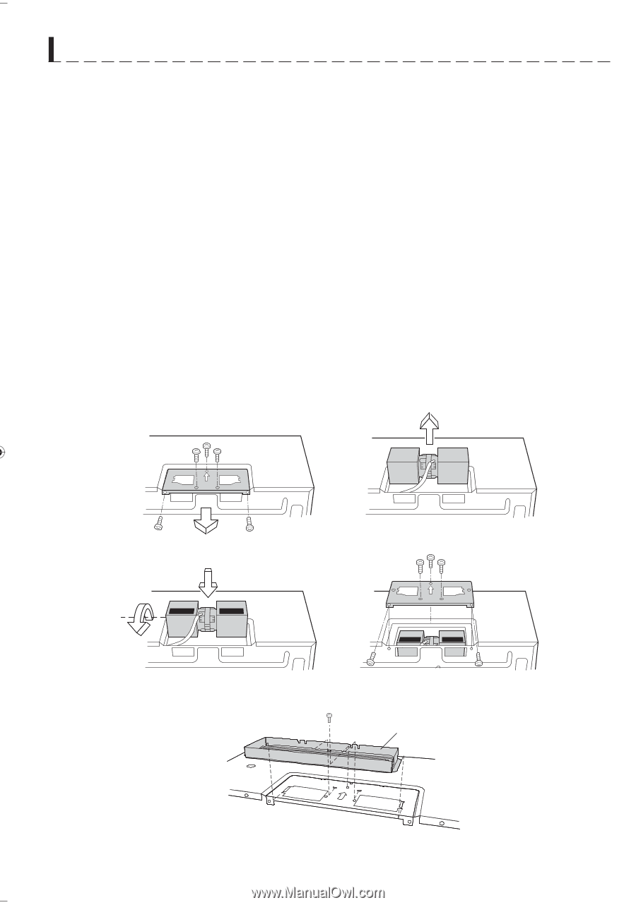
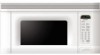
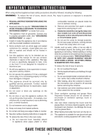
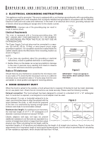
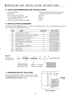
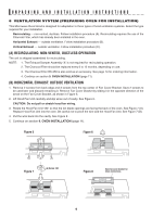
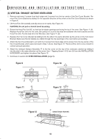
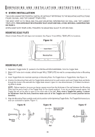
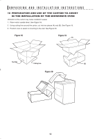
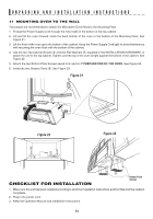
UNPACKING AND INSTALLATION INSTRUCTIONS (C) VERTICAL EXHAUST: OUTSIDE VENTILATION 1. Remove and save 2 screws from back edge and 3 screws from the top center of the Fan Cover Bracket. Remove Fan Cover Bracket by sliding it in the opposite direction of the arrow on the Fan Cover Bracket as shown in Figure 9. 2. Lift Hood Fan Unit carefully and slip wires out of cavity. See Figure 10. CAUTION: Do not pull or stretch hood fan wiring. 3. Rotate the Hood Fan Unit 90˚ so that the fan blade openings are facing the top of the oven. See Figure 11 (A). Replace Hood Fan Unit into the oven. Be careful not to pinch the lead wire between the inner bracket and the Hood Fan Unit. Put the lead wire into Wire Box. See Figure 11 (B). 4. Replace the Fan Cover Bracket by sliding it into the slits in the same direction as the arrow on the Fan Cover Bracket. Make sure the fan blades are visible through the top openings in the oven before proceeding. 5. Attach the Fan Cover Bracket to unit with the 2 screws from back edge and 3 screws from the top center of the Fan Cover Bracket, which were removed in Step 1 above. See Figure 12. The Hood Fan Unit is now rotated for vertical exhaust operation. 6. Attach the Exhaust Damper Assembly 7 to the fan cover on the top of the outercase cabinet by sliding it into the slits in the same direction as the arrow. Use 1 Tapping Screw 4 X12 mm 4 from the INSTALLATION HARDWARE and tighten into place See Figure 13. 7. Continue on section 9. OVEN INSTALLATION (page 6). Figure 9 Figure 10 Figure 11 (B) (A) Rotate 90˚ Figure 12 Figure 13 Exhaust Damper Assembly 10
-
 1
1 -
2
-
3
-
4
-
 5
5 -
 6
6 -
 7
7 -
 8
8 -
 9
9 -
 10
10 -
 11
11 -
 12
12 -
 13
13 -
 14
14 -
 15
15 -
16
-
17
-
18
-
19
-
20
-
21
-
22
-
23
-
24
-
25
-
26
-
27
-
28
-
29
-
30
-
31
-
32
 |
 |