Sharp UP-3301 Installation Manual - Page 1

Sharp UP-3301 Manual

Page 1 highlights

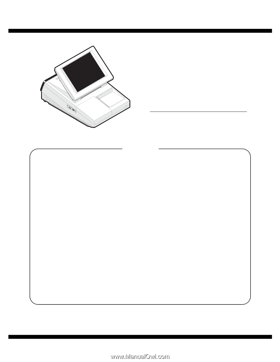
q INSTALLATION MANUAL CODE : 00ZUP3301VIME POS TERMINAL MODEL UP-3301 (For "V" version) CONTENTS 1. Removing the Rear display filter 2 2. Replacing the Rear display filter 2 3. Removing the Rear display 2 4. Replacing the Rear display 2 5. Removing the Top cabinet 3 6. Replacing the Top cabinet 3 7. Removing the Power transformer, NF PWB and AC cord 3 8. Replacing the Power transformer, NF PWB and AC cord 3 9. Removing the LCD unit 4 10. Replacing the LCD unit 5 11. Expansion RAM Board : UP-S02MB2M 5 12. RS232 I/F: ER-A7RS2 5 13. EFT I/F: ER-02EF2 6 14. MCR UNIT: UP-E12MR2 6 15. DRAWER BOX UNIT: ER-03DW/04DW/05DW 6 16. REMOTE DISPLAY : UP-P16DP 6 17. HOW TO EXTEND DISPLAY POLE 7 18. Built-in Printer: UP-T80BP 8 19. LAN 12 20. RS232 I/F: STANDARD 12 Parts marked with "!" are important for maintaining the safety of the set. Be sure to replace these parts with specified ones for maintaining the safety and performance of the set. SHARP CORPORATION This document has been published to be used for after sales service only. The contents are subject to change without notice.

  • 1
  • 2

INSTALLATION MANUAL
CODE : 00Z
q
CONTENTS
Parts marked with "
!
" are important for maintaining the safety of the set. Be sure to replace these parts with specified
ones for maintaining the safety and performance of the set.
SHARP CORPORATION
This document has been published to be used
for after sales service only.
The contents are subject to change without notice.
UP3301VIME
POS TERMINAL
MODEL
UP-3301
1.
Removing the Rear display filter . . . . . . . . . . . . . . . . . . . . . . . . . . . . . . . 2
2.
Replacing the Rear display filter . . . . . . . . . . . . . . . . . . . . . . . . . . . . . . . 2
3.
Removing the Rear display . . . . . . . . . . . . . . . . . . . . . . . . . . . . . . . . . . . 2
4.
Replacing the Rear display . . . . . . . . . . . . . . . . . . . . . . . . . . . . . . . . . . . 2
5.
Removing the Top cabinet . . . . . . . . . . . . . . . . . . . . . . . . . . . . . . . . . . . . 3
6.
Replacing the Top cabinet . . . . . . . . . . . . . . . . . . . . . . . . . . . . . . . . . . . . 3
7.
Removing the Power transformer, NF PWB and AC cord . . . . . . . . . . . . 3
8.
Replacing the Power transformer, NF PWB and AC cord . . . . . . . . . . . . 3
9.
Removing the LCD unit . . . . . . . . . . . . . . . . . . . . . . . . . . . . . . . . . . . . . . 4
10.
Replacing the LCD unit . . . . . . . . . . . . . . . . . . . . . . . . . . . . . . . . . . . . . . 5
11.
Expansion RAM Board : UP-S02MB2M. . . . . . . . . . . . . . . . . . . . . . . . . . 5
12.
RS232 I/F: ER-A7RS2 . . . . . . . . . . . . . . . . . . . . . . . . . . . . . . . . . . . . . . . 5
13.
EFT I/F: ER-02EF2 . . . . . . . . . . . . . . . . . . . . . . . . . . . . . . . . . . . . . . . . . 6
14.
MCR UNIT: UP-E12MR2 . . . . . . . . . . . . . . . . . . . . . . . . . . . . . . . . . . . . . 6
15.
DRAWER BOX UNIT: ER-03DW/04DW/05DW. . . . . . . . . . . . . . . . . . . . 6
16.
REMOTE DISPLAY : UP-P16DP. . . . . . . . . . . . . . . . . . . . . . . . . . . . . . . 6
17.
HOW TO EXTEND DISPLAY POLE . . . . . . . . . . . . . . . . . . . . . . . . . . . . 7
18.
Built-in Printer: UP-T80BP . . . . . . . . . . . . . . . . . . . . . . . . . . . . . . . . . . . . 8
19.
LAN . . . . . . . . . . . . . . . . . . . . . . . . . . . . . . . . . . . . . . . . . . . . . . . . . . . . 12
20.
RS232 I/F: STANDARD . . . . . . . . . . . . . . . . . . . . . . . . . . . . . . . . . . . . . 12
(For "V" version)