Sharp XE-A202 Service Manual
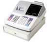
Sharp XE-A202 - Electronic Cash Register Manual
 |
UPC - 074000048270
View all Sharp XE-A202 manuals
Add to My Manuals
Save this manual to your list of manuals |
Sharp XE-A202 manual content summary:
- Sharp XE-A202 | Service Manual - Page 1
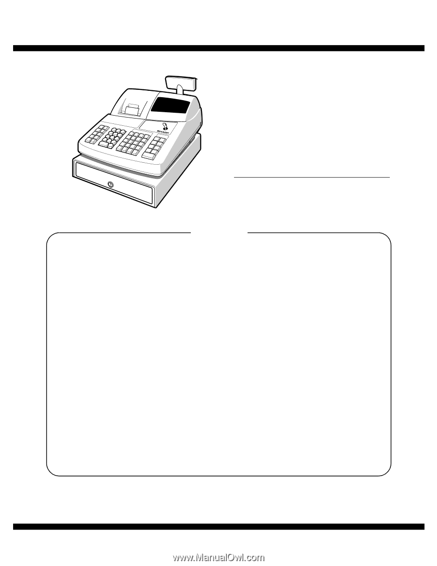
q SERVICE MANUAL CODE : 00ZXEA202USME ELECTRONIC CASH REGISTER MODEL XE-A202 (U and A version) CONTENTS CHAPTER 1. SPECIFICATIONS 1 CHAPTER 2. OPTIONS 5 CHAPTER 3. MASTER RESET AND PROGRAM RESET 5 CHAPTER 4. HARDWARE DESCRIPTION 6 CHAPTER 5. TEST FUNCTION 12 CHAPTER 6. IPL (INITIAL PROGRAM - Sharp XE-A202 | Service Manual - Page 2
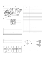
consumption Working temperature XE-A202 16.3lb (7.4kg) 13.0 (W) x 16.9 (D) x 11.0 (H) inches (330 (W) x 428 (D) x 280 (H) mm) AC 120V (m10%), 60Hz Stand-by 7.7W, Operating 30W (max.) 0°C~40°C (32°F to 104°F) 3. KEYBOARD 1) KEYBOARD LAYOUT Type Key position Key pitch Key layout Normal keyboard - Sharp XE-A202 | Service Manual - Page 3
each repeat. When you have registered ten times, the display will key to display the time. sMachine state symbols : Appears during programming. : Appears when an error key entry when the electronic journal (EJ) memory is full. (Depending on programming transaction when the electronic journal (EJ) - Sharp XE-A202 | Service Manual - Page 4
= error code P F: Light up when a registration is finalized by depressing CASH, CHECK, CHARGE key PGM selection) 6. PRINTER 1) Printer • Part number : M-T53II • NO. of station end sensor : Set up • Cutter : Manual Cutter • Near end sensor : No XE-A202U SPECIFICATIONS - 3 - 57.5±0.5 (Paper dimension) ( - Sharp XE-A202 | Service Manual - Page 5
) Location of the lock: Front Method of locking and unlocking: To lock, insert the drawer lock key into the lock and turn it 90 degrees counter clockwise. To unlock, insert the drawer lock key and turn it 90 degrees clockwise. Key No: SK1-1 ck ck SK1-1 Lo unlo XE-A202U SPECIFICATIONS - 4 - - Sharp XE-A202 | Service Manual - Page 6
roll paper PARTS CODE TPAPR6656RC05 4. SPECIAL SERVICE TOOLS NO NAME 1 RS-232 Loop-back connector 2 POS tools3 (IPL Software) PARTS CODE UKOG-6705RCZZ - PRICE RANK BA DESCRIPTION 5 ROLLS/PACK 70 φ PRICE RANK BC - DESCRIPTION Supplied by software CHAPTER 3. MASTER RESET AND PROGRAM RESET - Sharp XE-A202 | Service Manual - Page 7
STANDARD DRAWER. DRIVER , SENSOR CPU ROM : 256K Byte RAM : 20K Byte Data bus Address bus RAM 128K Byte PRINTER M-T53II PAPER TAKE UP MOTOR 4 to 16 DECORDER Seg. DRIVER Dig. DRIVER POPUP FRONT LED KEY SCAN SIGNAL KEYBOARD MODE SWITCH KEY RETURN SIGNAL RS232C DRIVER RS232 XE-A202U - Sharp XE-A202 | Service Manual - Page 8
Key IN 3 TB4IN P94 In Key IN 4 TB3IN P93 In Key IN 5 SOUT3 P92 In Key IN 6 SIN3 P91 In Key IN 7 CLK3 P90 In Key IN 8 BYTE VDD In VDD 9 CNVss CNVss In Normal : L Booting : H 10 XCIN XCIN In Calender clock :32.768KHz 11 XCOUT XCOUT In Calender clock :32 P73 Out Drawer drive 2 - Sharp XE-A202 | Service Manual - Page 9
VSS Print head temperature check VDD VDD Key IN 3. CLOCK GENERATOR 1) CPU 15 XIN CPU 13 XOUT 12MHz R 11 330 XCOUT 10 XCIN X1 32.768KHz C C 18P 27P Two oscillators are R20 2.7K 5 8 6 4 IC4B BA10393 7 /POFF C15 0.1uF ZD4 MTZJ5.1B P-OFF XE-A202U HARDWARE DESCRIPTION - 8 - - Sharp XE-A202 | Service Manual - Page 10
, the P-OFF signal is driver to LOW by the comparator 74 P16 73 P17 Signal used IN1 IN2 ENA1 ENA2 Drive step Driver IC input (CPU output) Motor drive signal STEP IN1 IN2 elements and head drivers which drives and register synchronizing with the CLOCK (CP) and stored in the latch register - Sharp XE-A202 | Service Manual - Page 11
register Shift register Thermal head strobe terminals STB No. 1 2 Dot No. 1 ~ 144 145 ~ 288 13 STB2 7 LAT 16 CLK 17 DAT 12 VCC Connector Number of dots 144 144 9. DRAWER -9 /S1 /S3 Paper Head up feed key sensor /S4 /S9 Paper end sensor RS232 XE-A202U HARDWARE DESCRIPTION - 10 - - Sharp XE-A202 | Service Manual - Page 12
PGM (OFF) TIME REG MGR X1/Z1 X2/Z2 position 3) Paper feed key Scan signal: 1 /S1 signal Return signal: 1 P91 signal The paper feed key is read by the above signals. 4) Head up sensor Scan signal: 1 ER 5 GND 6 DR 7 RS 8 CS 9 CI D-SUB 9pin connector XE-A202U HARDWARE DESCRIPTION - 11 - - Sharp XE-A202 | Service Manual - Page 13
Drawer 1 open & sensor test 9 120 External RAM test 10 121 CPU internal RAM test 11 140 CPU internal ROM test 12 160 AD conversion port test 13 500 RS232C test 14 550 Sleep mode test 2. DESCRIPTION OF EACH DIAGNOSTIC PROGRAM 1) DISPLAY BUZZER TEST 1 Key TEST 1 Key operation 102 - Sharp XE-A202 | Service Manual - Page 14
day hour min sec 8) DRAWER 1 OPEN AND SENSOR TEST 1 Key operation 110 RCPT/PO 2 Test procedure Display 1 1 0 X X: O = DRAWER OPEN C = DRAWER CLOSED 3 Check that: A) The drawer opens normally. B) The sensor correctly indicates the status of the drawer 1. *On the XE-A202, "C" (CLOSED) is always - Sharp XE-A202 | Service Manual - Page 15
If an error occurs at a step, the error is printed. If an error does not error 01 ER DR error 02 ER CI error 03 RS CD error 04 RS CD error 05 SD RD error DATA data 06 SD RD error DATA error/framing error 14) Sleep mode test 1 Key operation 550 RCPT/PO 2 Test procedure The test program - Sharp XE-A202 | Service Manual - Page 16
CPU supplied as a service part does not include the application program in it, the application program must be written when the CPU is replaced with a new one. To write the application program into the Flash ROM, connect the PC and the XE-A202 with an RS-232C cable, and execute the PC software. *Use - Sharp XE-A202 | Service Manual - Page 17
When connecting the RS-232 cable to the XE-A202, be sure to observe the following condiiton: Use RS-232 cable (with core) of accessories. [This is a necessary to support the EMI (Electronics Magnetic Interface).] RS232C CABLE CORE The accessory RS-232C cable has the following internal connections - Sharp XE-A202 | Service Manual - Page 18
46 45 44 43 42 41 40 39 38 37 36 35 34 33 32 31 FSCK FRD FSD /FR ES SOUT4 CLK4 TB4IN TB3IN SOUT3 SIN3 CLK3 27pF 1 0 R61 X2 3 2 3.3K 10uF/10V,OS 32.768KHz CST12.0 MTW C40 330pF R62 10K VDD C58 C59 + 0.1uF XE-A201 : 10uF/10V,OS XE-A202 : 10uF/16V,AL /ST B2 202V4/6/7 C108 33 91pF - Sharp XE-A202 | Service Manual - Page 19
XE-A202U CIRCUIT DIAGRAM AND PWB LAYOUT - 18 - 8 7 6 5 4 3 2 1 2/4 VH VH S6 D14 1SS133 R103 22K C81 0.1uF FB4 C66673 JUMPER WIRE KRC111S Q10 CN3 VCC VLED VP CN4A P91 P91 R104 4.7K 34 33 32 C74 B 31 30 a b a 0.1uF 29 c b 28 d c 27 e d 26 f e 25 g f 24 - Sharp XE-A202 | Service Manual - Page 20
XE-A202U CIRCUIT DIAGRAM AND PWB LAYOUT - 19 - 8 7 6 5 4 3 2 1 3/4 2021V4: 220V-230V 202V6/7:23 0V-240V POWER T RANS F1 D1 Q1:HEAT SINK 202U/A : 120 V D CN 1 3. 15A 1 2 1 2 - Sharp XE-A202 | Service Manual - Page 21
C94 FB11 FB12 FB13 /CI FB14 FB15 VCC /R S /ER /SD RD /CD /DR /C S 1000pF*5 /CD RD /SD /ER /DR /R S /C S /CI 5V C CN9 1 2 3 4 5 6 7 8 9 DB R50-09K1300 B XE-A202U CIRCUIT DIAGRAM AND PWB LAYOUT - 20 - A A 8 7 6 5 4 3 2 1 - Sharp XE-A202 | Service Manual - Page 22
XE-A202U CIRCUIT DIAGRAM AND PWB LAYOUT - 21 - 8 7 6 2. PRINTER I/F PWB CIRCUIT D CN4C 1 2 3 4 5 6 7 8 9 C 10 11 12 ONLY HOLE B A 8 CN4D 1 2 3 4 5 6 7 8 9 10 11 12 ONLY HOLE 7 6 5 4 3 2 VP VCC C201 0. - Sharp XE-A202 | Service Manual - Page 23
PWB LAYOUT 1. MAIN PWB LAYOUT A. side XE-A202U CIRCUIT DIAGRAM AND PWB LAYOUT - 22 - - Sharp XE-A202 | Service Manual - Page 24
B. side XE-A202U CIRCUIT DIAGRAM AND PWB LAYOUT - 23 - - Sharp XE-A202 | Service Manual - Page 25
2. KEY INTERFACE PWB LAYOUT A. side B. side 3. PRINTER I/F PWB LAYOUT XE-A202U CIRCUIT DIAGRAM AND PWB LAYOUT - 24 - - Sharp XE-A202 | Service Manual - Page 26
4. REAR DISPLAY PWB LAYOUT 5. DISPLAY PWB LAYOUT XE-A202U CIRCUIT DIAGRAM AND PWB LAYOUT - 25 - - Sharp XE-A202 | Service Manual - Page 27
. Printed in Japan. No part of this publication may be reproduced, stored in a retrieval system, or transmitted. In any form or by any means, electronic, mechanical, photocopying, recording, or otherwise, without prior written permission of the publisher. SHARP CORPORATION Digital Document Systems
-
 1
1 -
 2
2 -
 3
3 -
 4
4 -
 5
5 -
 6
6 -
 7
7 -
8
-
9
-
10
-
11
-
12
-
13
-
14
-
15
-
16
-
17
-
18
-
19
-
20
-
21
-
22
-
23
-
24
-
25
-
26
-
27
 |
 |
CODE : 00Z
q
SERVICE MANUAL
CONTENTS
Parts marked with "
!
" are important for maintaining the safety of the set. Be sure to replace these parts with specified
ones for maintaining the safety and performance of the set.
SHARP CORPORATION
This document has been published to be used
for after sales service only.
The contents are subject to change without notice.
XEA202USME
ELECTRONIC
CASH REGISTER
MODEL
XE-A202
(U and A version)
CHAPTER 1.
SPECIFICATIONS . . . . . . . . . . . . . . . . . . . . . . . . . . . . 1
CHAPTER 2.
OPTIONS . . . . . . . . . . . . . . . . . . . . . . . . . . . . . . . . . . . 5
CHAPTER 3.
MASTER RESET AND PROGRAM RESET. . . . . . . . . 5
CHAPTER 4.
HARDWARE DESCRIPTION . . . . . . . . . . . . . . . . . . . . 6
CHAPTER 5.
TEST FUNCTION . . . . . . . . . . . . . . . . . . . . . . . . . . . . 12
CHAPTER 6.
IPL (INITIAL PROGRAM LOADING) FUNCTION. . . . 15
CHAPTER 7.
CAUTION TO BE USED WHEN
CONNECTING THE RS-232 CABLE . . . . . . . . . . . . . 16
CHAPTER 8.
CIRCUIT DIAGRAM AND PWB LAYOUT . . . . . . . . . 17