Sharp XL-HP500 Service Manual - Page 38
has dropouts.
 |
View all Sharp XL-HP500 manuals
Add to My Manuals
Save this manual to your list of manuals |
Page 38 highlights
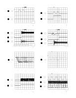
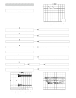
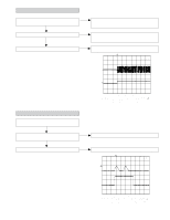
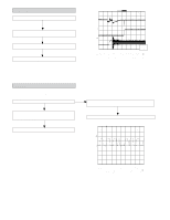
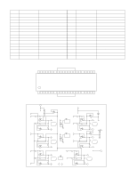
XL-HP500 (4) PLL system check. When a disc is loaded, start play operation. The HF waveform is normal, but the TOC data cannot be read. Check the PDO waveform. (Figure 38-1) Check around pins 73~78 on IC1. Stopped CH1=500 mV DC 10:1 PDO1 3 CH3=1 V DC 10:1 1999/04/05 17:33:17 CH4=1 V DC 10:1 500 ms/div (500 ms/div) NORM:20 kS/s 4 PDO2 T FDO 1 =Filter= Smoothing : ON BW : FULL =Offset= CH1 : 0.000 V CH2 : 0.0 V CH3 : 0.00 V CH4 : 0.00 V CH1 v/DIV 500 mV =Record Length= Main : 100 K Zoom : 2 K =Trigger= Mode : AUTO Type : EDGE CH2 Delay : 0.0 ns Hold off : 0.2 µs Figure 38-1 (5) Others. The HF waveform is normal and the time is displayed normally, but no sound is produced. Or the sound has dropouts. Is pin 52 (C2F) on IC1 "L" ? No Yes 1. When playing at normal speed. Check the peripheral circuit at pin 39 (DOUT) on IC1 and the waveform (Figure 38-2). If OK, Check the unit. There are too many error flags on a damaged disc which makes error correction impossible. Check again using a known good disc. Stopped T CH1=2 V DC 10:1 T 1999/04/07 09:25:28 500 ns/div (500 ns/div) NORM:200 MS/s 1 DOUT =Filter= Smoothing : ON BW : FULL =Offset= CH1 : 0.00 V CH2 : 0.00 V CH3 : 0.00 V CH4 : 0.00 V =Record Length= Main : 1 K Zoom : 100 =Trigger= Mode : NORMAL Type : EDGE CH1 Delay : 2.887 ms Hold off : 0.2 µs Figure 38-2 - 38 -
-
 1
1 -
2
-
3
-
4
-
5
-
6
-
7
-
8
-
9
-
10
-
11
-
12
-
13
-
14
-
15
-
16
-
17
-
18
-
19
-
20
-
21
-
22
-
23
-
24
-
25
-
26
-
27
-
28
-
29
-
30
-
31
-
32
-
 33
33 -
 34
34 -
 35
35 -
 36
36 -
 37
37 -
 38
38 -
 39
39 -
 40
40 -
 41
41 -
 42
42 -
 43
43 -
44
-
45
-
46
-
47
-
48
-
49
-
50
-
51
-
52
-
53
-
54
-
55
-
56
-
57
-
58
-
59
-
60
 |
 |
