Sony BDV-N990W Speaker Installation Guide - Page 2
English, Français, Español
 |
View all Sony BDV-N990W manuals
Add to My Manuals
Save this manual to your list of manuals |
Page 2 highlights
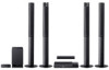
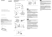
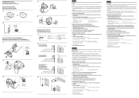
Installing speakers on a wall Installation des enceintes au mur Instalación de los altavoces en una pared Preparing the tall-type speaker Préparation de l'enceinte colonne Preparación del altavoz de tipo alto 1 2 Colored tube Tube coloré Tubo de color Preparing the satellite speaker (BDV-N890W only) Préparation de l'enceinte satellite (BDV-N890W uniquement) Preparación del altavoz de satélite (sólo en el modelo BDV-N890W ) 1 Colored tube Tube coloré Tubo de color 2 3 Colored tube Tube coloré Tubo de color 4 5 Hanging the speaker on the wall Accrochage de l'enceinte au mur Colocación del altavoz en la pared 1 4 mm (3/16 in / 3/16 po / 3/16 pulg) 30 mm (1 3/16 in / 1 3/16 po / 1 3/16 pulg) 5 mm (7/32 in / 7/32 po / 7/32 pulg) 10 mm (13/32 in / /13 32 po / /13 32 pulg) Hole on the back of the speaker Orifice situé au dos de l'enceinte Orificio de la parte posterior del altavoz 2 For the tall-type speaker Pour l'enceinte colonne Para el altavoz de tipo alto 200 mm (7 7/8 in / 7 7/8 po / 7 7/8 pulg) 8 mm to 10 mm (11/32 in to /13 32 in) 8 mm à 10 mm (11/32 po à /13 32 po) de 8 mm a 10 mm (11/32 pulg a /13 32 pulg) For the center speaker Pour l'enceinte centrale Para el altavoz central 4 mm to 6 mm (3/16 in to 1/4 in) 4 mm à 6 mm (3/16 po à 1/4 po) de 4 mm a 6 mm (3/16 pulg a 1/4 pulg) For the satellite speaker (BDV-N890W only) Pour l'enceinte satellite (BDV-N890W uniquement) Para el altavoz de satélite (solamente para el BDV-N890W) 5 mm to 7 mm (7/32 in to 9/32 in) 5 mm à 7 mm (7/32 po à 9/32 po) de 5 mm a 7 mm (7/32 pulg a 9/32 pulg) 154 mm (6 1/8 in / 6 1/8 po / 6 1/8 pulg) 40 mm (1 5/8 in / 1 5/8 po / 1 5/8 pulg) 3 English Caution Contact a screw shop or installer regarding the wall material or screws to be used. Use screws that are suitable for the wall material and strength. As a plaster board wall is especially fragile, attach the screws securely to a beam and fasten them to the wall. Install the speakers on a vertical and flat wall where reinforcement is applied. Sony is not responsible for accidents or damage caused by improper installation, insufficient wall strength or improper screw installation, natural calamity, etc. Preparing the tall-type speaker 1 Attach the speaker-bottom cover to the bottom of the upper part of the talltype speaker. 2 Connect the speaker cord to the speaker. Be sure to match the speaker cords to the appropriate terminals on the speakers: the speaker cord with the color tube to , and the speaker cord without the color tube to . Tube colors: Front left speaker (L): White Surround left speaker (L)*: Blue Front right speaker (R): Red Surround right speaker (R)*: Gray * BDV-N990W only. Preparing the satellite speaker (BDV-N890W only) 1 Remove the screw, then remove the stand and speaker cord. 2 Change the direction of the removed stand and thread the speaker cord through the hole of the stand. 3 Connect the speaker cord to the speaker. 4 Secure the stand with the screw that you removed in Step 1. 5 Secure the speaker cord in the speaker cord holder . Hanging the speaker on the wall 1 Prepare screws (not supplied) that are suitable for the hole on the back of each speaker. 2 Fasten the screws to the wall. Leave a space between the wall and the head of the screw. For the tall-type speaker: 8 mm to 10 mm For the satellite speaker*: 5 mm to 7 mm For the center speaker: 4 mm to 6 mm Measure the distance between the screws before fastening the screws to the wall. For the tall-type speaker: 200 mm For the center speaker: 154 mm For the satellite speaker*: 40 mm * BDV-N890W only. 3 Hang the speaker on the screws. Français Avertissement Adressez-vous à un quincaillier ou à un installateur pour connaître le matériau du mur ou les vis à utiliser. Utilisez des vis adaptées au matériau et à la résistance du mur. Comme les plaques de plâtre sont particulièrement fragiles, fixez fermement les vis à une poutre et fixez-les au mur. Installez les enceintes sur une paroi verticale et plane à un endroit où se trouve un renforcement. Sony ne peut être tenu responsable de tout accident ou dégât entraîné par une installation incorrecte, une résistance insuffisante du mur, une mauvaise fixation des vis, une catastrophe naturelle, etc. Préparation de l'enceinte colonne 1 Fixez le couvercle inférieur de l'enceinte au dessous de la partie supérieure de l'enceinte colonne. 2 Raccordez le cordon d'enceinte à l'enceinte. Veillez à faire correspondre les cordons d'enceinte aux bornes appropriées des enceintes : le cordon d'enceinte doté du tube coloré à et le cordon d'enceinte dépourvu de tube coloré à . Couleurs de tube : Enceinte avant gauche (L) : Blanc Enceinte avant droite (R) : Rouge Enceinte gauche surround (L)* : Bleu Enceinte droite surround (R)* : Gris * BDV-N990W uniquement. Préparation de l'enceinte satellite (BDV-N890W uniquement) 1 Retirez la vis, puis le support et le cordon d'enceinte. 2 Changez la direction du support que vous avez retiré et faites passer le cordon d'enceinte à travers l'orifice du support. 3 Raccordez le cordon d'enceinte à l'enceinte. 4 Fixez le support à l'aide de la vis que vous avez retirée à l'étape 1. 5 Fixez le cordon d'enceinte au support du cordon d'enceinte . Accrochage de l'enceinte au mur 1 Préparez des vis (non fournies) adaptées à l'orifice situé au dos de chaque enceinte. 2 Fixez les vis au mur. Laissez un espace entre le mur et la tête de la vis. Pour l'enceinte colonne : 8 mm à 10 mm Pour l'enceinte satellite* : 5 mm à 7 mm Pour l'enceinte centrale : 4 mm à 6 mm Mesurez la distance entre les vis avant de les fixer au mur. Pour l'enceinte colonne : 200 mm Pour l'enceinte centrale : 154 mm Pour l'enceinte satellite* : 40 mm * BDV-N890W uniquement. 3 Accrochez l'enceinte aux vis. Español Precaución Consulte con una tienda especializada en tornillos o con un instalador acerca del material de pared o de los tornillos que se deben utilizar. Utilice tornillos adecuados para el material y la resistencia de la pared. Dado que una pared de yeso es especialmente frágil, acople los tornillos firmemente a una viga y fíjelos en la pared. Instale los altavoces en una pared vertical y lisa que esté reforzada. Sony no se responsabiliza de ningún accidente o daño causado por una instalación inadecuada, una pared de poca resistencia, una instalación incorrecta de los tornillos, una catástrofe natural, etc. Preparación del altavoz de tipo alto 1 Coloque las cubiertas inferiores para los altavoces en la base de la parte superior del altavoz de tipo alto. 2 Conecte el cable de altavoz al altavoz. Asegúrese de que los cables de altavoz coincidan con los terminales adecuados de los altavoces: el cable de altavoz con el tubo de color en y el cable de altavoz sin el tubo de color en . Colores de los tubos: Altavoz frontal izquierdo (L): blanco Altavoz frontal derecho (R): rojo Altavoz de sonido envolvente izquierdo (L)*: azul Altavoz de sonido envolvente derecho (R)*: gris * Sólo BDV-N990W. Preparación del altavoz de satélite (sólo en el modelo BDV-N890W ) 1 Extraiga el tornillo y, a continuación, retire el soporte y el cable de altavoz. 2 Cambie la dirección del soporte retirado y pase el cable de altavoz por el orificio del soporte. 3 Conecte el cable de altavoz al altavoz. 4 Fije el soporte con el tornillo que quitó en el Paso 1. 5 Fije el cable de altavoz en el soporte para el cable de altavoz . Colocación del altavoz en la pared 1 Prepare unos tornillos (no suministrados) que sean adecuados para el orificio situado en la parte posterior de cada altavoz. 2 Fije los tornillos en la pared. Deje un espacio entre la pared y la cabeza del tornillo. Para el altavoz de tipo alto: de 8 a 10 mm Para el altavoz de satélite*: de 5 a 7 mm Para el altavoz central: de 4 a 6 mm Mida la distancia entre los tornillos antes de fijarlos a la pared. Para el altavoz de tipo alto: 200 mm Para el altavoz central: 154 mm Para el altavoz de satélite*: 40 mm * Sólo BDV-N890W. 3 Cuelgue el altavoz en los tornillos.
-
 1
1 -
 2
2
 |
 |
