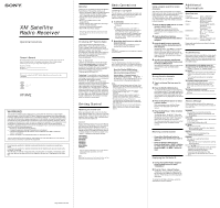
Sony CDX-CA900X XM Satellite Radio Operating manual - Page 2
Installation, Connection - wiring
 |
View all Sony CDX-CA900X manuals
Add to My Manuals
Save this manual to your list of manuals |
Page 2 highlights
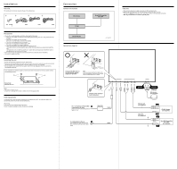
Installation Parts list The numbers in the list are keyed to those in the instructions. 1 2 3 4 ø4 × 14 mm × 4 5.5m 5.5m 5.5m Precautions • Choose the mounting location carefully, observing the following: - The unit is not subject to temperatures exceeding 55°C (131°F) (such as in a car parked in direct sunlight). - The unit is not subject to direct sunlight. - The unit is not near heat sources (such as heaters). - The unit is not exposed to rain or moisture. - The unit is not exposed to excessive dust or dirt. - The unit is not subject to excessive vibration. - The fuel tank should not be damaged by the tapping screws. - There should be no wire harnesses or pipes under the place where you are going to install the unit. - The spare tire, tools or other equipment in or under the trunk should not be interfered with or damaged by the screws or the unit itself. • Be sure to use only the supplied mounting hardware for a safe and secure installation. • Use only the supplied screws. Installing the unit •Mount the unit either inside the trunk or under a seat. •Choose the mounting location carefully so the unit will not interfere with the normal movements of the driver and it will not be exposed to direct sunlight or hot air from the heater. •Do not install the unit under the floor carpet, where the heat dissipation from the unit will be considerably impaired. First, place the unit where you plan to install it, and mark the positions of the four screw holes on the mounting surface. 1 1 Screw hole: ø3.3 mm (5/32 in.) Notes • Use only the supplied screws. • Be sure not to damage the fuel tank or brake line with the tapping screws. Fuse replacement If the fuse blows, check the power connection and replace the fuse. If the fuse blows again after replacement, there may be an internal malfunction. Warning Use a fuse with the specified amperage rating. Use of a higher amperage fuse may cause serious damage. Connection Connection example XM Antenna* XT-XM1 CD/MD changer* Connection diagram Sony BUS Compatible Car Audio* Cautions • This unit is designed for negative ground 12 V DC operation only. • Before making connections, turn the car ignition off to avoid short circuits. • Connect the yellow power input cord only after all other cords have been connected. • Run all ground leads to a common ground point. * not supplied Connect with BUS cable to the XM Satellite receiver, aligning the v marks. Note When you use an optional BUS cable, note that a BUS cable with an 8-pin plug (L-type) cannot be used because of its shape. POWER SONY BUS CONTROL OUT IN AUDIO L OUT R L IN R ANTENNA TER SAT 2 Connect as the connector hook facing down Green Yellow (Curry) XM antenna (not supplied) To a +12 V power terminal which is energized at all times Be sure to connect the black ground lead to it first. Fuse (3 A) Yellow To a metal point on the car First connect the black ground lead, then connect the yellow power input leads. Black RCA pin cord (not supplied) BUS cable (not supplied) 4 3 OUT OUT IN CD/MD changer (not supplied) Sony BUS Compatible Car Audio (not supplied) IN
-
 1
1 -
 2
2
 |
 |
