Sony CDX GT310 Installation Instructions - Page 2
Abnehmen der Schutzumrandung
 |
UPC - 027242699779
View all Sony CDX GT310 manuals
Add to My Manuals
Save this manual to your list of manuals |
Page 2 highlights
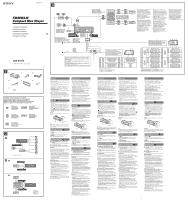
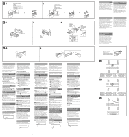
1 Orient the release key correctly. Richten Sie den Löseschlüssel korrekt aus. Orientez correctement la clé de déblocage. Orientare la chiavetta di rilascio nel modo corretto. Plaats de ontgrendelingssleutel op de juiste manier. 1 182 mm 53 mm 2 2 Face the hook inwards. Der Haken muss nach innen weisen. Tournez le crochet vers l'intérieur. Con il gancetto rivolto verso l'interno. Het haakje moet naar binnen wijzen. Claws Klammern Griffes Morsetti Klemhaken 3 Dashboard Armaturenbrett Tableau de bord Cruscotto Dashboard Fire wall Motorraumtrennwand Paroi ignifuge Parete tagliafiamma Brandschot A B Precautions • Choose the installation location carefully so that the unit will not interfere with normal driving operations. • Avoid installing the unit in areas subject to dust, dirt, excessive vibration, or high temperature, such as in direct sunlight or near heater ducts. • Use only the supplied mounting hardware for a safe and secure installation. Mounting angle adjustment Adjust the mounting angle to less than 45°. Removing the protection collar and the bracket Before installing the unit, remove the protection collar and the bracket from the unit. 1 Remove the protection collar . Engage the release keys together with the protection collar . Pull out the release keys to remove the protection collar . 2 Remove the bracket . Insert both release keys together between the unit and the bracket until they click. Pull down the bracket , then pull up the unit to separate. Mounting example Installation in the dashboard Notes • Bend these claws outward for a tight fit, if necessary (-2). • Make sure that the 4 catches on the protection collar are properly engaged in the slots of the unit (-3). How to detach and attach the front panel Before installing the unit, detach the front panel. -A To detach Before detaching the front panel, be sure to press Press , and pull it off towards you. -B To attach Engage part of the front panel with part of the unit, as illustrated, and push the left side into position until it clicks. Warning if your car's ignition has no ACC position Be sure to set the Auto Off function. For details, see the supplied Operating Instructions. The unit will shut off completely and automatically in the set time after the unit is turned off, which prevents battery drain. If you do not set the Auto Off function, press and hold until the display disappears each time you turn the ignition off. RESET button When the installation and connections are completed, be sure to press the RESET button with a ball-point pen, etc., after detaching the front panel. Sicherheitshinweise • Wählen Sie den Einbauort sorgfältig so aus, dass das Gerät beim Fahren nicht hinderlich ist. • Bauen Sie das Gerät so ein, dass es keinen hohen Temperaturen (keinem direkten Sonnenlicht, keiner Warmluft von der Heizung), keinem Staub, keinem Schmutz und keinen starken Vibrationen ausgesetzt ist. • Für eine sichere Befestigung verwenden Sie stets die mitgelieferten Montageteile. Hinweis zum Montagewinkel Das Gerät sollte in einem Winkel von weniger als 45° montiert werden. Abnehmen der Schutzumrandung und der Halterung Nehmen Sie vor dem Installieren des Geräts die Schutzumrandung und die Halterung vom Gerät ab. 1 Entfernen Sie die Schutzumrandung . Setzen Sie beide Löseschlüssel an der Schutzumrandung an. Ziehen Sie die Schutzumrandung mithilfe der Löseschlüssel heraus. 2 Entfernen Sie die Halterung . Führen Sie beide Löseschlüssel zwischen dem Gerät und der Halterung ein, bis sie mit einem Klicken einrasten. Ziehen Sie die Halterung nach unten und das Gerät nach oben, um die beiden zu trennen. Montagebeispiel Installation im Armaturenbrett Hinweise • Falls erforderlich, biegen Sie diese Klammern für einen sicheren Halt nach außen (-2). • Achten Sie darauf, die 4 Verriegelungen an der Schutzumrandung korrekt in die Aussparungen am Gerät einzusetzen (-3). Abnehmen und Anbringen der Frontplatte Nehmen Sie die Frontplatte vor dem Einbau des Geräts ab. -A Abnehmen Schalten Sie das Gerät vor dem Abnehmen der Frontplatte unbedingt mit aus. Drücken Sie und ziehen Sie sie auf sich zu heraus. -B Anbringen Setzen Sie Teil der Frontplatte wie in der Abbildung dargestellt an Teil des Geräts an und drücken Sie die linke Seite der Frontplatte an, bis sie mit einem Klicken einrastet. Warnhinweis, wenn die Zündung Ihres Fahrzeugs nicht über eine Zubehörposition (ACC oder I) verfügt Aktivieren Sie unbedingt die Abschaltautomatik. Näheres dazu finden Sie in der mitgelieferten Bedienungsanleitung. Nach dem Ausschalten wird das Gerät dann nach der voreingestellten Zeit automatisch vollständig abgeschaltet, so dass der Autobatterie kein Strom mehr entzogen wird. Wenn Sie die Abschaltautomatik nicht aktivieren, müssen Sie jedes Mal, wenn Sie die Zündung ausschalten, die Taste gedrückt halten, bis die Anzeige ausgeblendet wird. Taste RESET Wenn Sie das Gerät eingebaut und alle Anschlüsse vorgenommen haben, müssen Sie die Frontplatte abnehmen und mit einem Kugelschreiber oder einem anderen spitzen Gegenstand die Taste RESET drücken. Précautions • Choisissez soigneusement l'emplacement de l'installation afin que l'appareil ne gêne pas la conduite normale du véhicule. • Evitez d'installer l'appareil dans un endroit exposé à de la poussière, de la saleté, des vibrations violentes ou à des températures élevées, comme en plein soleil ou à proximité d'un conduit de chauffage. • Pour garantir un montage sûr, n'utilisez que le matériel fourni. Réglage de l'angle de montage Réglez l'inclinaison à un angle inférieur à 45°. Retrait du tour de protection et du support Avant d'installer l'appareil, retirez le tour de protection et le support de l'appareil. 1 Retirez le tour de protection . Enclenchez les clés de déblocage simultanément dans le tour de protection . Tirez sur la clé de déblocage pour retirer le tour de protection . 2 Retirez le support . Insérez les deux clés de déblocage simultanément entre l'appareil et le support jusqu'au déclic indiquant qu'elles sont en place. Tirez le support vers le bas, puis tirez l'appareil vers le haut pour les séparer. Exemple de montage Installation dans le tableau de bord Remarques • Pliez ces griffes vers l'extérieur pour assurer une prise correcte si nécessaire (-2). • Assurez-vous que les 4 loquets du tour de protection sont correctement insérés dans les fentes de l'appareil (-3). Retrait et fixation de la façade Avant d'installer l'appareil, retirez la façade. -A Pour la retirer Avant de retirer la façade, n'oubliez pas d'appuyer sur Appuyez ensuite sur , puis faites glisser la façade vers vous. -B Pour la fixer Fixez la partie de la façade sur la partie de l'appareil, comme indiqué sur l'illustration, puis appuyez sur le côté gauche jusqu'au déclic. Avertissement si le contact de votre voiture ne comporte pas de position ACC Veillez à régler la fonction de mise hors tension automatique. Pour obtenir davantage d'informations, reportez-vous au mode d'emploi fourni. L'appareil s'éteint complètement et automatiquement après le laps de temps choisi une fois l'appareil mis hors tension afin d'éviter que la batterie ne se décharge. Si vous ne réglez pas la fonction de mise hors tension automatique, appuyez sur la touche et maintenezla enfoncée jusqu'à ce que l'affichage disparaisse à chaque fois que vous coupez le contact. Touche RESET Une fois que l'installation et les raccordements sont terminés, retirez la façade et appuyez sur la touche RESET à l'aide d'un stylo à bille ou d'un autre objet pointu. Precauzioni • Scegliere con attenzione la posizione per l'installazione in modo che l'apparecchio non interferisca con le operazioni di guida del conducente. • Evitare di installare l'apparecchio dove sia soggetto ad alte temperature, come alla luce solare diretta o al getto di aria calda dell'impianto di riscaldamento, o dove possa essere soggetto a polvere, sporcizia e vibrazioni eccessive. • Usare solo il materiale di montaggio in dotazione per un'installazione stabile e sicura. Regolazione dell'angolo di montaggio Regolare l'angolo di montaggio in modo che sia inferiore a 45°. Rimozione della staffa e della cornice protettiva Prima di installare l'apparecchio, rimuovere la cornice protettiva e la staffa dall'apparecchio. 1 Rimuovere la cornice protettiva . Inserire le chiavette di rilascio nella cornice protettiva . Per rimuovere la cornice di protettiva estrarre le chiavette di rilascio . 2 Rimuovere la staffa . Inserire contemporaneamente entrambe le chiavette di rilascio tra l'apparecchio e la staffa fino a che non scattano in posizione. Estrarre la staffa , quindi sollevare l'apparecchio per rimuoverlo. Esempio di montaggio Installazione nel cruscotto Note • Piegare verso l'esterno questi morsetti per un'installazione più sicura, se necessario (-2). • Assicurarsi che i 4 fermi sulla cornice protettiva siano correttamente inseriti negli alloggiamenti dell'apparecchio (-3). Rimozione e applicazione del pannello anteriore Prima di installare l'apparecchio rimuovere il pannello anteriore. -A Per rimuoverlo Prima di rimuovere il pannello anteriore, premere Premere , quindi tirare verso di sé il pannello anteriore. -B Per reinserirlo Applicare la parte del pannello anteriore alla parte dell'apparecchio come mostrato nell'illustrazione e premere il lato sinistro fino a sentire uno scatto. Avvertenza relativa all'installazione su un'auto sprovvista della posizione ACC (accessoria) sul blocchetto di accensione Accertarsi di impostare la funzione di spegnimento automatico. Per ulteriori informazioni, fare riferimento alle istruzioni per l'uso in dotazione. L'apparecchio si spegne completamente e automaticamente all'ora impostata dopo che è stato disattivato, onde evitare che la batteria si scarichi. Se la funzione di spegnimento automatico non è stata impostata, ogni volta che il motore viene spento tenere premuto nché il display non viene disattivato. Tasto RESET Una volta completate le procedure di installazione e i collegamenti, accertarsi di premere il tasto RESET con una penna a sfera o un oggetto simile dopo avere rimosso il pannello anteriore. Voorzorgsmaatregelen • Kies de installatieplaats zorgvuldig zodat het apparaat de bestuurder niet hindert tijdens het rijden. • Installeer het apparaat niet op plaatsen waar het blootgesteld wordt aan hoge temperaturen, b.v. in direct zonlicht of bij de warme luchtstroom van de autoverwarming, aan sterke trillingen, of waar het in contact komt met veel stof of vuil. • Gebruik voor het veilig en stevig monteren van het apparaat uitsluitend de bijgeleverde montageonderdelen. Maximale montagehoek Installeer het apparaat nooit onder een hoek van meer dan 45° met het horizontale vlak. De beschermende rand en de beugel verwijderen Voordat u het apparaat gaat installeren, moet u de beschermende rand en de beugel verwijderen van het apparaat. 1 Verwijder de beschermende rand . Bevestig de ontgrendelingssleutels op de beschermende rand . Trek de ontgrendelingssleutels naar u toe om de beschermende rand te verwijderen. 2 Verwijder de beugel . Plaats de ontgrendelingssleutels tussen het apparaat en de beugel tot deze vastklikken. Trek de beugel omlaag en trek het apparaat omhoog om deze van elkaar te scheiden. Montagevoorbeeld Montage in het dashboard Opmerkingen • Indien nodig kunt u deze klemhaken ombuigen voor een steviger bevestiging (-2). • De 4 grepen op de beschermende rand moeten goed in de sleuven van het apparaat zijn geplaatst (-3). Het voorpaneel verwijderen en bevestigen Verwijder, alvorens met het installeren te beginnen, het voorpaneel. -A Verwijderen Vergeet niet, voordat u het voorpaneel verwijdert, eerst op te drukken. Druk vervolgens op de toets en trek het naar u toe. -B Bevestigen Breng deel van het voorpaneel aan op deel van het apparaat zoals afgebeeld en druk op de linkerzijde tot deze vastklikt. Waarschuwing als het contactslot van de auto geen ACC-positie heeft Zorg ervoor dat u de functie voor automatisch uitschakelen instelt. Raadpleeg de bijgeleverde gebruiksaanwijzing voor meer informatie. Het apparaat wordt na de ingestelde tijd automatisch volledig uitgeschakeld nadat het apparaat is uitgeschakeld. Zo wordt voorkomen dat de accu leegloopt. Als u de functie voor automatisch uitschakelen niet instelt, moet u ingedrukt houden tot het display verdwijnt telkens wanneer u het contact uitschakelt. RESET-toets Als u de installatie en aansluitingen hebt voltooid, moet u met een puntig voorwerp, zoals de punt van een balpen, op RESET drukken nadat u het voorpaneel hebt verwijderd. Power connection diagram Auxiliary power connector may vary depending on the car. Check your car's auxiliary power connector diagram to make sure the connections match correctly. There are three basic types (illustrated below). You may need to switch the positions of the red and yellow leads in the car stereo's power connecting lead. After matching the connections and switched power supply leads correctly, connect the unit to the car's power supply. If you have any questions and problems connecting your unit that are not covered in this manual, please consult the car dealer. Diagramma dei collegamenti di alimentazione Il connettore di alimentazione ausiliaria può variare a seconda della macchina. Controllare il diagramma del connettore di alimentazione ausiliaria della macchina per essere sicuri che i collegamenti corrispondano correttamente. Vi sono tre tipi di base (illustrazione sotto). Potrà essere necessario cambiare le posizioni dei fili rosso e giallo nel cavo di alimentazione dello stereo della macchina. Dopo aver fatto corrispondere i collegamenti e aver commutato i cavi di alimentazione, collegare l'apparecchio all'alimentazione della macchina. Se si hanno domande o se sorgono problemi che non sono stati trattati nel manuale nel collegare l'apparecchio, contattare l'autoconcessionario. Stromanschlussdiagramm Der Hilfsstromanschluss kann je nach Fahrzeugtyp unterschiedlich sein. Sehen Sie im Hilfsstromanschlussdiagramm für Ihr Fahrzeug nach, wie die Verbindung ordnungsgemäß vorgenommen werden muss. Es gibt, wie unten abgebildet, drei grundlegende Typen. Sie müssen möglicherweise die rote und gelbe Leitung des Stromversorgungskabels der Autostereoanlage vertauschen. Stellen Sie die Anschlüsse her, schließen Sie die geschalteten Stromversorgungsleitungen richtig an und verbinden Sie dann das Gerät mit der Stromversorgung Ihres Fahrzeugs. Wenn beim Anschließen des Geräts Fragen oder Probleme auftreten, die in dieser Bedienungsanleitung nicht erläutert werden, wenden Sie sich bitte an den Autohändler. Voedingsaansluitschema De hulpvoedingsaansluiting kan verschillen afhankelijk van de auto. Controleer het hulpvoedingsaansluitschema dat bij dit apparaat wordt geleverd om te zien of de aansluitingen kloppen. Er zijn drie basistypes (zie afbeelding hieronder). Het is mogelijk dat u de posities van de rode en gele kabels in de voedingskabel van het car audiosysteem moet omwisselen. Als de aansluitingen en geschakelde voedingskabels kloppen, sluit u het apparaat aan op de voeding van de auto. Indien u nog vragen of problemen hebt in verband met het aansluiten van het apparaat die niet in deze handleiding vermeld staan, raadpleeg dan de autodealer. Schéma de raccordement d'alimentation Le connecteur d'alimentation auxiliaire peut varier suivant le type de voiture. Vérifiez le schéma du connecteur d'alimentation auxiliaire de votre voiture pour vous assurer que les connexions correspondent. Il en existe trois types de base (illustrés ci-dessous). Il se peut que vous deviez commuter la position des câbles rouge et jaune du câble d'alimentation de l'autoradio. Après avoir établi les connexions et commuté correctement les câbles d'alimentation, raccordez l'appareil à l'alimentation de la voiture. Si vous avez des questions ou des difficultés à propos de cet appareil qui ne sont pas abordées dans le présent mode d'emploi, consultez votre concessionnaire automobile. Auxiliary power connector Hilfsstromanschluss Connecteur d'alimentation auxiliaire Connettore di alimentazione ausiliaria Hulpvoedingsaansluiting Red Rot Rouge Rosso Rood Red Rot Rouge Rosso Rood Yellow Gelb Jaune Giallo Geel Yellow Gelb Jaune Giallo Geel Yellow continuous power supply Red switched power supply Gelb permanente Stromversorgung Rot geschaltete Stromversorgung 4 Jaune alimentation continue 7 Rouge alimentation commutée Giallo alimentazione continua Rosso alimentazione commutata Geel continu voeding Rood geschakelde voeding Red Rot Rouge Rosso Rood Red Rot Rouge Rosso Rood Yellow Gelb Jaune Giallo Geel Yellow Gelb Jaune Giallo Geel Yellow switched power supply Red continuous power supply Gelb geschaltete Stromversorgung Rot permanente Stromversorgung 4 Jaune alimentation commutée 7 Rouge alimentation continue Giallo alimentazione commutata Rosso alimentazione continua Geel geschakelde voeding Rood continu voeding Red Rot Rouge Rosso Rood Red Rot Rouge Rosso Rood Yellow Gelb Jaune Giallo Geel Yellow Gelb Jaune Giallo Geel the car without ACC position Fahrzeug ohne Zubehörposition (ACC) Véhicule sans position ACC Auto priva della posizione ACC Auto zonder ACC-positie
-
 1
1 -
 2
2
 |
 |
