Sony DRC-BT15 Operating Instructions - Page 7
Location and Function of Parts - strap
 |
UPC - 027242714090
View all Sony DRC-BT15 manuals
Add to My Manuals
Save this manual to your list of manuals |
Page 7 highlights
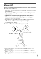
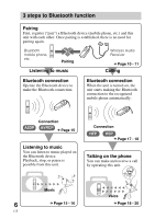
GETTING STARTED Location and Function of Parts 9 q; 1 2 3 78 4 5 6 . VOL x N . VOL POWER qa 1 Headphones jack 2 Strap hole 3 Clip hole 4 Indicator (red) Indicates the power status of the unit. 5 Microphone 6 Multi function button Controls various call functions. 7 Indicator (blue) Indicates the communication status of the unit. 8 Jog switch Controls various functions when listening to music. Adjust the volume of the unit when talking over the telephone. 9 RESET button 0 Contact point qa POWER button 7 US
-
 1
1 -
 2
2 -
 3
3 -
 4
4 -
 5
5 -
 6
6 -
 7
7 -
 8
8 -
 9
9 -
 10
10 -
 11
11 -
 12
12 -
13
-
14
-
15
-
16
-
17
-
18
-
19
-
20
-
21
-
22
-
23
-
24
-
25
-
26
-
27
-
28
-
29
-
30
-
31
-
32
-
33
-
34
-
35
-
36
-
37
-
38
-
39
-
40
-
41
-
42
-
43
-
44
-
45
-
46
-
47
-
48
-
49
-
50
-
51
-
52
-
53
-
54
-
55
-
56
 |
 |

7
US
VOL
POWER
VOL
.
.
Nx
7
9
q;
4
1
3
2
5
6
qa
8
Location and Function of Parts
1
Headphones jack
2
Strap hole
3
Clip hole
4
Indicator (red)
Indicates the power status of the
unit.
5
Microphone
6
Multi function button
Controls various call functions.
7
Indicator (blue)
Indicates the communication
status of the unit.
8
Jog switch
Controls various functions
when listening to music.
Adjust the volume of the unit
when talking over the
telephone.
9
RESET button
0
Contact point
qa
POWER button
GETTING STARTED