Sony F35 Product Manual (CAF101 Operations Manual 1st ED) - Page 20
Locations and Functions of Parts
 |
View all Sony F35 manuals
Add to My Manuals
Save this manual to your list of manuals |
Page 20 highlights
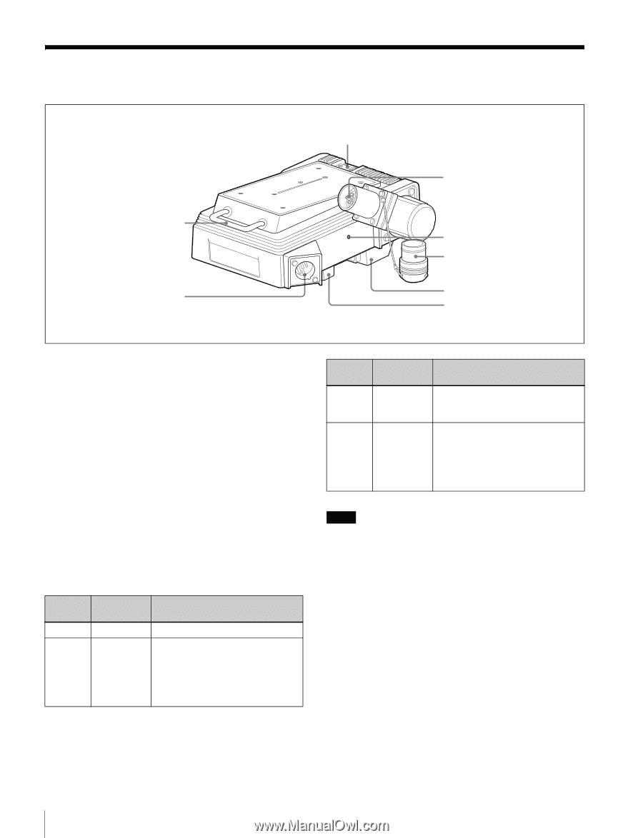
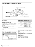
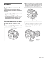
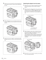
Locations and Functions of Parts a Cable hanger b DC IN connector Viewfinder shoe receptacle (see page 23) c VTR connector DC IN 10.5-17V OPT d OPT indicator Rubber cap for the VTR connector e Camera connector 1 f Camera connector 2 a Cable hanger You can fix cables on this, using bundlers. b DC IN connector (XLR 4-pin) Connecting the BKP-L551 Battery Adaptor or a specified power cable, supply power to the camera and this unit. This is effective only when this unit is mounted on the rear of the camera. c VTR connector (optical/electric composite connector, female) Connect to the CAMERA connector of the HKSR-101 mounted on the SRPC-1 using a hybrid optical camera cable. d OPT (optical level) indicator It lights up when communication between the camera and recorder is established, indicating the optical level status. Lighting Meaning color Measures to be taken Green Normal level Yellow Cautioning level Sufficient for operation, but the optical contacts may have some dirt. It is recommended to clean the optical contacts of the unit and the cable (see page 26). Lighting Meaning color Measures to be taken Red Warning Immediately clean the optical level contacts of the unit and the cable (see page 26). Unlit No signal, or Immediately clean the optical unusable contacts of the unit and the cable level (see page 26). If the indicator remains unlit, check the connections and the recorder operation. Note The optical level is also decreased if the camera cable between the camera and the recorder is long or has many junctions. e Camera connector 1 Video/audio and control signals are sent/received to/from the camera. f Camera connector 2 Power is sent/received to/from the camera. For details on power supply, see page 24. 20 Locations and Functions of Parts
-
 1
1 -
2
-
3
-
4
-
5
-
6
-
7
-
8
-
9
-
10
-
11
-
12
-
13
-
14
-
 15
15 -
 16
16 -
 17
17 -
 18
18 -
 19
19 -
 20
20 -
 21
21 -
 22
22 -
 23
23 -
 24
24 -
 25
25 -
26
-
27
-
28
-
29
-
30
-
31
-
32
 |
 |