Sony FX41 Operating Instructions - Page 13
INPUT A/INPUT B, OUTPUT, REMOTE, AC IN socket, CONTROL S IN/PLUG IN POWER, DC 5V output jack stereo
 |
UPC - 027242754775
View all Sony FX41 manuals
Add to My Manuals
Save this manual to your list of manuals |
Page 13 highlights
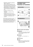
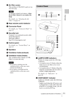
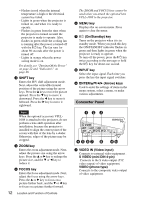
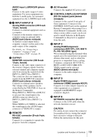
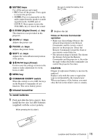
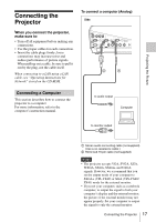
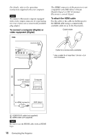
Overview AUDIO input L (MONO)/R (phono type) Connect to the audio output of video equipment. For stereo equipment use both the L and R jacks; for monaural equipment use the L (MONO) jack only. 2/3 INPUT A/INPUT B Analog RGB connector (HD D-sub 15-pin, female) Connects to external equipment such as a computer. Connects to the monitor output of a computer using an optional cable. AUDIO jack (stereo minijack) To listen to sound output from a computer, connect via this jack to the audio output of the computer. For details, see "Connecting a Computer" on page 17 and "Connecting a VCR" on page 19. d OUTPUT MONITOR connector (HD D-sub 15-pin, female) Connect to the video input connector of the monitor. Outputs signals from the selected channel and computer signals only from among the signals from the INPUT A, INPUT B or INPUT C. This connector does not output any signals from the INPUT D connector. AUDIO jack (stereo minijack) Connects to external active speakers. The volume of the speakers can be controlled by the VOLUME +/- keys on the Remote Commander. When INPUT A, INPUT B or INPUT C is selected, the sound input to the AUDIO connector which is for INPUT A, INPUT B or INPUT C is output. When VIDEO or S VIDEO is selected, the sound input to the AUDIO input connector of VIDEO IN is output. e REMOTE RS-232C connector (D-sub 9-pin, female) Connects to a computer to operate the projector from the computer. f AC IN socket Connects the supplied AC power cord. g CONTROL S IN/PLUG IN POWER (DC 5V output) jack (stereo minijack) Connects to the control S out jacks of Sony equipment. Connects to the CONTROL S OUT jack on the supplied Remote Commander when using it as a wired Remote Commander. In this case, when a stereo cable is used, you do not need to install batteries in the Remote Commander as the power is supplied from this jack. h INPUT C Analog RGB/Component connectors (R/R-Y/PR, G/Y, B/B-Y/ PB, HD, VD) (BNC type) We recommend using this terminal when signals are to be transmitted over greater distance than usual, such as when the projector is suspended from a ceiling. Computer, component (R-Y/Y/B-Y), HDTV or DTV (DTV GBR, DTV YPBPR) signal can be selected. AUDIO (stereo mini-jack) Connects to the audio output on a computer. i INPUT D Digital RGB/Component connector (HDMI) (accepts HDCP) Connects to a video output connector on video equipment or a computer equipped with HDMI/DVI output connector (digital). j INPUT E NETWORK connector (RJ-45) Connects to the LAN cable when the network function is in use. CAUTION For safety, do not connect the connector for peripheral device wiring that might have excessive voltage to this port. Follow the instructions for this port. Location and Function of Controls 13
-
 1
1 -
2
-
3
-
4
-
5
-
6
-
7
-
 8
8 -
 9
9 -
 10
10 -
 11
11 -
 12
12 -
 13
13 -
 14
14 -
 15
15 -
 16
16 -
 17
17 -
 18
18 -
19
-
20
-
21
-
22
-
23
-
24
-
25
-
26
-
27
-
28
-
29
-
30
-
31
-
32
-
33
-
34
-
35
-
36
-
37
-
38
-
39
-
40
-
41
-
42
-
43
-
44
-
45
-
46
-
47
-
48
-
49
-
50
-
51
-
52
-
53
-
54
-
55
-
56
-
57
-
58
-
59
 |
 |
