Sony KDL-46XBR10 Operating Instructions - Page 14
PC Input Signal Reference Chart, Shown with PC connection, Picture, Wide Mode, Scene Select, Graphics
 |
UPC - 027242753150
View all Sony KDL-46XBR10 manuals
Add to My Manuals
Save this manual to your list of manuals |
Page 14 highlights
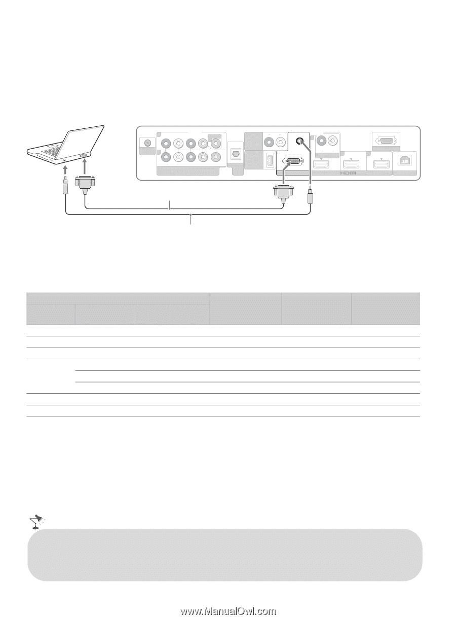
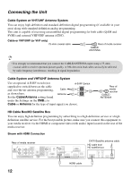
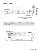
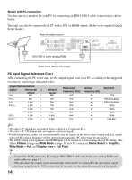
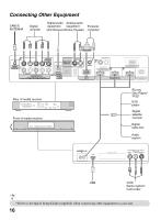
Shown with PC connection Use this unit as a monitor for your PC by connecting an HD15-HD15 cable connection as shown below. This unit can also be connected to a PC with a DVI or HDMI output. (Refer to the supplied Quick Setup Guide.) Rear of media receiver 1 CABLE/ ANTENNA 2 VIDEO IN 1 R AUDIO L PR PB Y COMPONENT IN (1080p/1080i/720p/480p/480i) R AUDIO L AUDIO OUT (VAR/FIX) AUDIO (OPTICAL) DIGITAL AUDIO OUT DMex/ SERVICE RGB PC IN 1 R AUDIO L AUDIO IN 3 REMOTE 4 IN LAN HD15-HD15 cable (analog RGB) Audio cable (stereo mini plugs) PC Input Signal Reference Chart After connecting the PC to the unit, set the output signal from your PC according to the supported resolutions and timings indicated below. Supported resolutions Signal VGA Horizontal × (Pixel) 640 × SVGA 800 × XGA 1,024 × WXGA 1,280 × 1,280 × 1,360 × SXGA 1,280 × HDTV* 1,920 × Vertical (Line) 480 600 768 768 768 768 1,024 1,080 Horizontal Vertical frequency (kHz) frequency (Hz) 31.5 60 37.9 60 48.4 60 47.4 60 47.8 60 47.7 60 64.0 60 67.5 60 Standard VGA VESA Guidelines VESA Guidelines VESA VESA VESA VESA CEA-861* ~ • This unit's PC input does not support Sync on Green or Composite Sync. • This unit's PC VGA input does not support interlaced signals. • For the best picture quality, it is recommended to use the signals in the above chart. In plug and play, signals with a 60 Hz vertical frequency will be detected automatically. (PC reboot may be necessary.) * The 1080p timing when applied to the HDMI input will be treated as a video timing and not PC timing. This affects Picture settings and Wide Mode settings. To view PC content set Scene Select to Graphics, Wide Mode to Full, and Display Area to Full Pixel. • Connect the PC IN jack to the PC using an HD15-HD15 cable with ferrite core (analog RGB) and audio cable (see page 11). • The unit enters the standby mode automatically when the PC is connected to the unit and no signal has been output from the PC for more than 30 seconds, see the online Reference Book for details. 14
-
 1
1 -
2
-
3
-
4
-
5
-
6
-
7
-
8
-
 9
9 -
 10
10 -
 11
11 -
 12
12 -
 13
13 -
 14
14 -
 15
15 -
 16
16 -
 17
17 -
 18
18 -
 19
19 -
20
-
21
-
22
-
23
-
24
-
25
-
26
-
27
-
28
-
29
-
30
-
31
-
32
-
33
-
34
-
35
-
36
-
37
-
38
-
39
-
40
-
41
-
42
-
43
-
44
-
45
-
46
-
47
-
48
-
49
-
50
-
51
-
52
-
53
-
54
-
55
-
56
 |
 |