Sony KDL-52WL135 Installing the Wall-Mount Bracket (SU-WL500) - Page 2
Screw and Hook locations diagram/table, TV installation dimensions table
 |
View all Sony KDL-52WL135 manuals
Add to My Manuals
Save this manual to your list of manuals |
Page 2 highlights
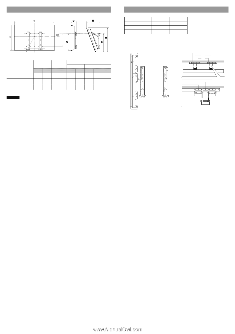
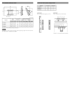
TV installation dimensions table 320 (12 5/8) Screen center point Model Name Display dimensions Screen center dimensions A B C KDL-40WL135 992 643 176 (39 1/8) (25 3/8) (7) KDL-46WL135 1135 734 (44 3/4) (29) 128 (5 1/8) KDL-52WL135 1278 (50 3/8) 832 (32 7/8) 73 (2 7/8) Figures in the above table may differ slightly depending on the installation. Unit: mm (inches) Length for each mounting angle Angle (0˚) Angle (20˚) D E F G H 518 (20 1/2) 519 (20 1/2) 519 (20 1/2) 182 (7 1/4) 182 (7 1/4) 183 (7 1/4) 345 (13 5/8) 376 (14 7/8) 410 (16 1/4) 620 (24 1/2) 706 (27 7/8) 797 (31 1/2) 557 (22) 558 (22) 555 (21 7/8) WARNING The wall that the TV will be installed on should be capable of supporting a weight of at least four times that of the TV. Refer to your TV's instructions for its weight. Screw and Hook locations diagram/table Model Name KDL-40WL135 KDL-46WL135 KDL-52WL135 Screw location e, g e, g d, g Hook location b b a Screw location When installing the Mounting Hook on the TV. d e d d e e f f f g g h h g j j h j Hook location When installing the TV onto the Base Bracket. a b c* * Hook position "c" cannot be used for the models in the table above.
-
 1
1 -
 2
2
 |
 |