Sony LF-V30 Operating Instructions - Page 8
What is the LocationFree, Base Station?, VIDEO 1 OUT S-VIDEO/VIDEO/AUDIO terminal
 |
UPC - 027242721258
View all Sony LF-V30 manuals
Add to My Manuals
Save this manual to your list of manuals |
Page 8 highlights
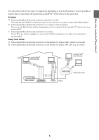
What is the LocationFree® Base Station? Rear VIDEO 1 IN OUT VIDEO 1 WLAN S VIDEO S VIDEO CLIENT AP VIDEO L AUDIO R Y PB PR VIDEO L LAN AUDIO R 1 Y IR BLASTER 2 PB PR VIDEO L AUDIO R VIDEO DC IN 12V L AUDIO R VIDEO 2 IN (VIDEO/COMPONENT) VIDEO 2 OUT (VIDEO/COMPONENT) 1 VIDEO 1 IN (S-VIDEO/VIDEO/AUDIO) terminal (1 page 13) Connect audio cables and either a video or S-Video cable. 2 VIDEO 2 IN (COMPONENT/VIDEO/AUDIO) terminal (1 page 13) Connect audio cables and either component video cables or a video cable. 3 VIDEO 1 OUT (S-VIDEO/VIDEO/AUDIO) terminal (1 page 13) Connect audio cables and either a video or S-Video cable. The VIDEO 1 OUT terminal outputs the signals input from the VIDEO 1 IN terminal. 4 WLAN switch (1 page 21) Changes the Wireless mode of the Base Station. If you set the switch to AP, the Base Station works in the Access Point mode, in which the Base Station connects to a router via a LAN cable and works as a wireless access point. If you set the switch to CLIENT, the Base Station works in the Client mode, in which the Base Station connects to a wireless router wirelessly. 5 LAN port (1 page 21) Connect a LAN cable. 6 IR BLASTER 1/2 port (1 page 16) Connect the IR Blaster (supplied). You can purchase another IR Blaster to connect to one of the ports. 7 VIDEO 2 OUT (COMPONENT/VIDEO/AUDIO) terminal (1 page 13) Connect audio cables and either component video cables or a video cable. The VIDEO 2 OUT terminal outputs the signals input from the VIDEO 2 IN terminal. 8 DC IN jack (1 page 11) Connect the AC power adapter (supplied). 8
-
 1
1 -
2
-
 3
3 -
 4
4 -
 5
5 -
 6
6 -
 7
7 -
 8
8 -
 9
9 -
 10
10 -
 11
11 -
 12
12 -
 13
13 -
14
-
15
-
16
-
17
-
18
-
19
-
20
-
21
-
22
-
23
-
24
-
25
-
26
-
27
-
28
-
29
-
30
-
31
-
32
-
33
-
34
-
35
-
36
-
37
-
38
-
39
-
40
-
41
-
42
 |
 |
