Sony LSPX-W1S Operating Instructions (Cabinet)
Sony LSPX-W1S Manual
 |
View all Sony LSPX-W1S manuals
Add to My Manuals
Save this manual to your list of manuals |
Sony LSPX-W1S manual content summary:
- Sony LSPX-W1S | Operating Instructions (Cabinet) - Page 1
Instructions (this manual) (1) Pin (6) (two for spare) Adjusting the foot height You can adjust the height by using the four feet at the bottom of the cabinet. For more details, refer to the operating instructions of the LSPX-W1 Video Projector board. © 2014 Sony Corporation Printed in Japan - Sony LSPX-W1S | Operating Instructions (Cabinet) - Page 2
To remove the top panel A Phillips-head screwdriver is necessary to remove the top panel. 1 After opening the door, push the latch into the cabinet. 2 Remove the four screws on the front side of the cabinet. 3 Slide the top panel toward the front side, and lift it up to remove. Latch Notes •
-
 1
1 -
 2
2
 |
 |
© 2014 Sony Corporation
Printed in Japan
Operating Instructions
Before operating the unit, please read this manual thoroughly and retain it for
future reference.
LSPX-WCB
4-544-120-
11
(1)
Cabinet
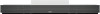
Notes on Loading Weight
Do not put anything on the cabinet heavier than shown in the figure above. If the weight exceeds the
specified value, the center board, or top panel may break.
Notes on Installation
•
Be careful not to pinch your hands or feet when installing the cabinet.
•
Depending on the installation location, deformation or inclination of the cabinet may occur. To prevent
this from occurring, be sure to do the following:
-
Install the cabinet at a level and firm floor.
-
Place a hard plate etc. under the cabinet when installing on soft material such as a carpet.
-
Do not place the cabinet in a location subject to direct sunlight or near a heating appliance.
-
Do not place the cabinet in a location subject to high temperature and humidity, or outdoors.
•
Be sure to do the following when moving the cabinet to avoid a serious injury:
-
Be sure to move the cabinet with two or more people.
•
The door of the cabinet opens and closes. If you place something beside the cabinet, place it at a distance
more than 1 mm from the cabinet.
•
Place the equipment inside the cabinet after adjusting the feet.
•
When moving the cabinet, do not drag it on the floor. Doing so may damage the floor.
•
If there is debris such as sand on the feet of the cabinet, the floor may be damaged.
10 kg (22 lb 0.74 oz)
7 kg (15 lb 6.9 oz)
25 kg (55 lb 1.8 oz)
Notes on Usage
•
Do not place sharp objects such as ceramic ware and vases on the cabinet. The top panel may be
damaged.
•
Do not place anything hot on the cabinet. The heat may cause discoloration or deformation to the cabinet.
•
To keep the cabinet in good condition, clean the cabinet gently with a soft dry cloth. If the cabinet
becomes extremely dirty, clean it gently with a soft cloth dampened with a mild detergent diluted with
water. Do not use chemical agents such as alcohol, paint thinners, and benzenes. They may damage the
coating of the cabinet.
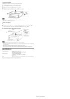
Checking the supplied accessories
•
Operating Instructions (this manual) (1)
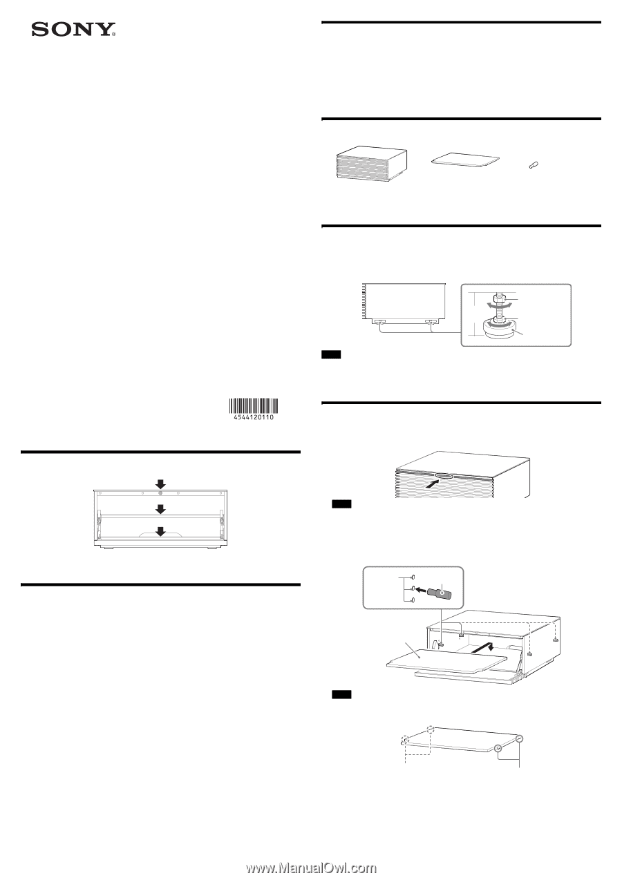
Adjusting the foot height
You can adjust the height by using the four feet at the bottom of the cabinet.
For more details, refer to the operating instructions of the LSPX-W1 Video Projector or the compatible
video projector.
•
Use a wrench with a 13 mm nominal diameter double-surface width or the adjustment tool included with
the LSPX-W1 Video Projector or the compatible video projector to adjust the feet.
•
If the foot height is more than 35 mm, the foot may come off and the cabinet may slant and result in
injury.
Storing equipment
1
Push the second step from the top on the front side of the cabinet to open the door.
•
Be careful not to pinch your hands or feet when opening or closing the door.
•
Do not push down on areas other than the center part. Doing so may bend the door and cause damage
to the backside of the door or the front side of the cabinet.
2
Attach the center board.
There are three attaching holes on the foreside and inner side of the left and right panels inside the
cabinet. Insert the pins aligning the desired height.
•
Attach the center board so that the cut parts on the left and right sides of the center board are
positioned on the front side.
•
Check that the pins are firmly fixed in the grooves on the rear surface of the center board.
•
Attach the four pins at the same height.
•
Check that the center board is not shaky, then place the equipment inside.
3
Store the equipment.
To store the equipment or cables, you can remove the top panel.
Notes
Notes
Notes
Center board (1)
Pin (6)
(two for spare)
Cabinet (1)
Side
Fixing nut
Foot
height
Foot
Adjusting nut
Center board
Pin
Attaching
hole
Groove
Groove