Sony MZ-N505 Service Manual
Sony MZ-N505 Manual
 |
View all Sony MZ-N505 manuals
Add to My Manuals
Save this manual to your list of manuals |
Sony MZ-N505 manual content summary:
- Sony MZ-N505 | Service Manual - Page 1
SERVICE MANUAL Ver 1.0 2002. 01 MZ-N505 US Model Canadian Model AEP Model UK Model US and foreign patents licensed from Dolby Laboratories. • OpenMG, "MagicGate", "MagicGate Memory Stick", "Memory Stick", VAIO,MusicClip and their logos are trademarks of Sony Corporation. • "WALKMAN" is a trademark - Sony MZ-N505 | Service Manual - Page 2
/8 × 3 in.) without projections. Mass Approx. 104 g (3.7 oz) the recorder only Supplied accessories NC-WMAA Nickel Cadmium rechargeable battery (European model only) (1) AC power adaptor (1) Headphones/earphones with a remote control (1) Optical cable (European model only) (1) USB cable (1) Battery - Sony MZ-N505 | Service Manual - Page 3
MZ-N505 come printed with the lead free mark due to their particular size) : LEAD FREE MARK Unleaded solder has the MT-MZN707-177 8 3-6. Set Chassis (5188) Assy 9 3-7. MAIN Board 9 3-8. OP Service Assy (LCX-5R 10 3-9. Holder Assy 11 3-10. DC Motor (Sled) (M602 11 8. ELECTRICAL PARTS LIST 60 3 - Sony MZ-N505 | Service Manual - Page 4
to "Net MD Help " of the online help. Note The optical digitaloutputconnector (on computers providedwithone) may be disabled duringplayback for the protection of copyrights. Notes on using OpenMG Jukebox with Windows 2000/Windows XP If your computer is Windows 2000 Professional, Windows XP Home - Sony MZ-N505 | Service Manual - Page 5
GENERAL MZ-N505 This section is extracted from instruction manual. Lookingat the controls The recorder 6 The display window of the recorder A disc and track names, error messages, track numbers, etc. N Play mode indication Shows play mode of the MD. 10 11 The headphones/earphoneswith a remote - Sony MZ-N505 | Service Manual - Page 6
MZ-N505 • This set can be disassembled in the order shown below. 3-1. DISASSEMBLY FLOW SECTION (Page 8) 3-5. MECHANISM DECK (MT-MZN707-177) (Page 8) 3-6. SET CHASSIS (5188) ASSY (Page 9) 3-8. OP SERVICE ASSY (LCX-5R) (Page 10) 3-7. MAIN BOARD (Page 9) 3-9. HOLDER ASSY (Page 11) 3-10. DC MOTOR - Sony MZ-N505 | Service Manual - Page 7
Note: Follow the disassembly procedure in the numerical order given. 3-2. CASE (LOWER) MZ-N505 1 two screws (M1.4) 1 two screws (M1.4) 2 Remove the case (lower) in the direction of the arrow. 3-3. CASE (UPPER) SECTION Set chassis (5188) assy 6 case (upper) - Sony MZ-N505 | Service Manual - Page 8
MZ-N505 3-4. LCD MODULE, CASE (UPPER) SUB ASSY 1 four screws (1.7 × 2.5) 2 LCD module Note: On installation, adjust the position of both switch and knob (hold). switch 3 button (control) 4 case (upper) sub assy knob (hold) 3-5. MECHANISM DECK (MT-MZN707-177) 3 step screw (MD) 6 mechanism deck (MT- - Sony MZ-N505 | Service Manual - Page 9
3-6. SET CHASSIS (5188) ASSY 2 two screws (1.7 × 2.5) MZ-N505 3 set chassis (5188) assy 3-7. MAIN BOARD 1 four screws (M1.4 × 2) 3 battery case 4 main board 1 battery terminal board (+) 2 battery terminal (-) 9 - Sony MZ-N505 | Service Manual - Page 10
MZ-N505 3-8. OP SERVICE ASSY (LCX-5R) 1 washer (0.8-2.5) 3 screw (M1.4) 4 rack spring 2 gear (SA) 5 screw (M1.4) 6 thrust detent spring 8 Pull off lead screw. 7 9 Opening the over write head toward the direction A, remove the OP service assy (LCX-5R) toward the direction B. B Note: Do not open - Sony MZ-N505 | Service Manual - Page 11
3-9. HOLDER ASSY MZ-N505 4 holder assy 2 Open the holder assy 1 convex portion 3 boss 3 boss 3-10. DC MOTOR (SLED) (M602) 2 washer (0.8-2.5) 4 two screws (M1.4) 5 DC motor (sled) (M602) 3 gear (SA) 1 Remove six solders of the motor flexible board. 11 - Sony MZ-N505 | Service Manual - Page 12
MZ-N505 3-11. DC SSM18B MOTOR (SPINDLE) (M601), DC MOTOR (OVER WRITE HEAD UP/DOWN) (M603) 1 Remove six solders of the motor flexible board. 2 tapping screw 3 motor - Sony MZ-N505 | Service Manual - Page 13
MZ-N505 OUTLINE • This set provides the Overall adjustment mode that allows CD and MO discs to be automatically adjusted when in the test mode. In this overall adjustment mode, the disc pressing the x key, press the keys on the remote commander with the following order: >t>t.t.t >t.t >t.tXtX Note - Sony MZ-N505 | Service Manual - Page 14
MZ-N505 CONFIGURATION OF TEST MODE [Test Mode $Display Check Mode%] Press the > or [VOL +] key [Manual Mode] Press the x key [Servo Adjustment] [Audio Adjustment] [Power Supply Adjustment] [OP Alignment Adjustment] Press the . or [VOL --] key [Overall Adjustment Mode] Press the x key [ - Sony MZ-N505 | Service Manual - Page 15
MZ-N505 5. The display changes a shown below each time the [MENU/ENTER] key . • 700's), only the item is displayed. 6. Quit the manual mode, and press the x key to return to the test mode (display check mode). 1 XX : Error code * * * * : Total recording time If the [MENU/ENTER] key is pressed with - Sony MZ-N505 | Service Manual - Page 16
MZ-N505 • Description of Error Indication Codes Problem No error Servo system error TOC error Power supply system error Offset system error Disc error Indication code 00 01 02 03 04 11 12 22 31 32 33 34 35 Meaning of code No error Illegal access target address was specified High temperature - Sony MZ-N505 | Service Manual - Page 17
MZ-N505 SOUND SKIP CHECK RESULT DISPLAY MODE This set can display the count of errors that occurred during the recording/playing for checking. • switch is operated. If any other key is pressed during this display, the remote commander LCD switches to its name display) Example1: When the > key - Sony MZ-N505 | Service Manual - Page 18
MZ-N505 4. When all the keys on the set and on the remote commander are considered as OK, the following displays are shown for 4 seconds. Example1: When the keys on the set are considered as OK: Set LCD display 888 SET OK Example2: When the keys on the remote commander are considered as OK: Set - Sony MZ-N505 | Service Manual - Page 19
mode. 2. Use the following tools and measuring instruments. • Test CD disc TDYS-1 (Part No. : 4-963-646-01) • SONY MO disc available on the market • Digital voltmeter • Laser power meter LPM-8001 (Part No. : J-2501-046-A) • Thermometer (using the Temperature Correction) 3. Unless specified - Sony MZ-N505 | Service Manual - Page 20
MZ-N505 • Change of NV Adjusted Values (version 1.100) Caution: Change the NV adjustment values according to the mi- crocomputer version. In this set, some adjusted values were set in the manual mode at the shipment, but these will be cleared when the NV is reset. Therefore, modify the NV adjusted - Sony MZ-N505 | Service Manual - Page 21
MZ-N505 23) Adjust with the [VOL +] key (adjusted value up) or [VOL --] key (adjusted value down) so that the adjusted value becomes 5B. 24) Press the X key to write the adjusted value. 25) Select manual key to write the adjusted value. 37) Select manual mode of the test mode, and set item number - Sony MZ-N505 | Service Manual - Page 22
MZ-N505 49) Select manual mode of the test mode, and set item number 871 (see page 14). ) so that the adjusted value becomes CA. 51) Press the X key to write the adjusted value. 52) Select manual mode of the test mode, and set item number 872 (see page 14). Set LCD display 872 ###: Address **: - Sony MZ-N505 | Service Manual - Page 23
MZ-N505 2. Press the X key to write the adjusted value. Adjustment and Connection Location: MAIN : MAIN board (See page 25) TEMPERATURE COREECTION • Adjustment Method of Temperature Correction 1. Select the manual mode of test mode, and set the item number 015 (see page 14). Set LCD display - Sony MZ-N505 | Service Manual - Page 24
MZ-N505 LASER POWER CHECK • Connection laser power meter Optical pick-up objective (-)) of resis- tor R521 at this time is below 80 mV. 13. Press the x key to quit the manual mode, and activate the test mode (display check mode). Checking and Connection Location: MAIN board (See page 25) MAIN - Sony MZ-N505 | Service Manual - Page 25
MZ-N505 Adjustment/checking and Connection Location: - MAIN Board (Component Side) - TP (−) CN501 C518 1 Q501 E C B L502 20 L501 L904 C904 + R519 R521 R522 F801 C630 L902 + R105 - Sony MZ-N505 | Service Manual - Page 26
MZ-N505 CD overall adjustment completed *1: Manual adjustment exists (overall adj. Caution: The electrical offset adjustment must be made with no disc loaded. 1. Make sure that the power supply voltage is 4. Press the [MENU/ENTER] key on the remote commander. Set LCD display 035 Ofst** 5. Electrical - Sony MZ-N505 | Service Manual - Page 27
MZ-N505 3. Insert CD disc LCD display 000 CD OK 6. Insert MO disc in the set, and press the > key error gain adjustment 328 CD TWPP gain adjustment 324 CD tracking error error gain adjustment 224 Low reflective CD tracking error MO tracking error gain adjustment MO tracking error offset adjustment - Sony MZ-N505 | Service Manual - Page 28
MZ-N505 RESUME CLEAR Perform the Resume clear when all adjustments completed. • Resume Clear Setting Method 1. Select the manual mode of the test mode, and set item number 043 (see page 14). Set LCD display 043 ###: Address 2. Press the X key. Set LCD display ###S00 - Sony MZ-N505 | Service Manual - Page 29
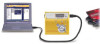
MZ-N505 service technical support division to get the application. • Pre-Check 1. Check the microcomputer version in this set. (For a checking method of the microcomputer version, see "SECTION 4 TEST MODE" (page 13).) 2. Check that the Net MD Driver window opens. 4. Click the [Usb Connect] button. 29 - Sony MZ-N505 | Service Manual - Page 30
MZ-N505 5. Confirm that the model and version indicated on the title bar coincide with the codes displayed in the Device Name block and the Version block in the window. 6. Click the [Write + Verify] button. The patch data writing and the verify processing will be executed automatically in the - Sony MZ-N505 | Service Manual - Page 31
8. Click the [Usb Disconnect] button. 9. Confirm that the window becomes as shown below where the [Write + Verify] button and [Read] button are inactive. 10. Disconnect the USB cable from the personal computer and the set. 31 31 MZ-N505 - Sony MZ-N505 | Service Manual - Page 32
MZ-N505 SECTION 6 DIAGRAMS 6-1. BLOCK DIAGRAM - SERVO/USB Section - OPTICAL PICK-UP BLOCK (LCX-5R) HR601 OVER WRITE HEAD OVER WRITE HEAD DRIVE Q604, 605 IY IX JX JX JY JX JY IX IY IX A A BC D B C D MON LD LD-A RF AMP, FOCUS/TRACKING ERROR EFM PRE DRIVER H-BRIDGE PRE DRIVER SYSTEM - Sony MZ-N505 | Service Manual - Page 33
MZ-N505 6-2. BLOCK DIAGRAM - AUDIO Section - (Page 32) A DIN1 VIF B+ B+ SWITCH Q302 ADDT (Page 32) B (Page 34) E SDO0, SCK0 AOUTL, (Page 32 ) C AOUTR SDO0 SCK0 SDI0 SDO0 - Sony MZ-N505 | Service Manual - Page 34
MZ-N505 6-3. BLOCK DIAGRAM - DISPLAY/KEY CONTROL/POWER SUPPLY Section - (Page 33) F RMC B+ VA A/D CONVERTER (IC301), SYSTEM CONTROLLER (IC801) B+ VC RF AMP (IC501), MOTOR/COIL DRIVER (IC551), REMOTE CONTROL CIRCUIT B+ NOISE FILTER NOISE FILTER VRECO OVER WRITE HEAD DRIVE (IC601) B+ VREC OVER WRITE - Sony MZ-N505 | Service Manual - Page 35
0 or dotted line with mark 0 are critical for safety. Replace only with part number specified. • A : B+ Line. • Total current is measured with MD installed. • Power voltage is dc 3 V and fed with regulated dc power its lead layout is different form that of conventional IC. 35 35 MZ-N505 - Sony MZ-N505 | Service Manual - Page 36
MZ-N505 • Semiconductor Location Ref. No. D601 D603 D607 D803 D804 D904 Location I-7 I-5 I-3 G-3 H-2 H-5 IC551 D-5 IC604 H-5 IC804 D-4 Q302 D-9 Q501 F-7 Q601 I-6 Q603 H-3 Q608 I-5 6-5. PRINTED WIRING BOARD - MAIN Board (Component - Sony MZ-N505 | Service Manual - Page 37
+ TP (VREC) 4 1 Q604 5 8 1-682-873- 11 (11) SWITCH & LCD MODULE J601 DC IN 3V - + HR601 OVER WRITE HEAD 37 37 MZ-N505 • Semiconductor Location Ref. No. D101 D201 D301 D602 D606 D608 D701 D703 D901 D902 D903 Location G-4 H-3 G-2 I-4 H-10 I-10 D-4 D-5 H-5 G-4 H-5 IC301 E-5 IC302 - Sony MZ-N505 | Service Manual - Page 38
MZ-N505 6-7. SCHEMATIC 2200p R505 10k 0.5% R517 1k 0.5% AREF ADIP RF AMP, FOCUS/TRACKING ERROR AMP IC501 SN761057ADBT ADIP TE -IN REXT WPP -LPF VREF C S-MON line with mark 0 are critical for safety. Replace only with part number specified. Les composants identifiés par une marque 0 sont - Sony MZ-N505 | Service Manual - Page 39
MZ-N505 6-8. SCHEMATIC DIAGRAM - MAIN Board (2/4) - • See page 42 for Waveform. • See page 43 for IC Block Diagrams. A1 A2 A3 A4 A5 A6 (Page 38) A7 - Sony MZ-N505 | Service Manual - Page 40
MZ-N505 NC NC NC NC NC NC NC NC NC DRAMVDD0 DRAMVDD1 DRAMVSS0 DRAMVSS1 NC NC NC NC NC NC NC NC NC NC DVSS0 DVDD0 - Sony MZ-N505 | Service Manual - Page 41
See page 42 for Waveforms. • See page 43 for IC Block Diagrams. MZ-N505 E1 E2 E3 E4 E5 (Page 40) E8 E9 E10 E11 C1 (Page mark 0 or dotted line with mark 0 are critical for safety. Replace only with part number specified. Les composants identifiés par une marque 0 sont critiques pour la sécurité. - Sony MZ-N505 | Service Manual - Page 42
MZ-N505 • Waveforms 1 IC501 1 (TE) 7 IC901 th (CLK) 200 mVp-p qs IC801 - Sony MZ-N505 | Service Manual - Page 43
22 12 VREF 11 LPF1 10 BST NF1 9 LPF2 BEEP OUTB 23 PW A PW B BEEP OUTA 24 12 3 4 BST2 BST AGC 5 6 8 BST NF2 7 BST OUT MZ-N505 VCC2 OUTA PWR GND OUTB DET AGC IN 43 - Sony MZ-N505 | Service Manual - Page 44
MZ-N505 IC501 SN761057A TE 1 REXT 2 Wpp LPF 3 VREF 4 C5 D6 D-C 7 Iy 8 Ix 9 Jx 10 Jy 11 A 12 A-C 13 B 14 TON-C 15 CIG 16 CDN 17 PD- - Sony MZ-N505 | Service Manual - Page 45
VG H-BRIDGE PRE DRIVER CH1 VC H-BRIDGE CONTROL CH2 28 FI2 27 RI2 26 COM2 25 CPUI2 24 CPVI2 23 CPWI2 22 NC 21 GND2 20 CPWI1 19 CPVI1 VC H-BRIDGE CONTROL CH1 18 CPUI1 17 COM1 16 RI1 15 FI1 34 5 6 7 8 9 10 11 12 13 14 MZ-N505 VI1 WI1 PGNDW1 WO1 - Sony MZ-N505 | Service Manual - Page 46
MZ-N505 IC601 XPC18A22AFCR2 VRECIN1 OUTA PGND2 PGND2 OUTB VRECIN2 VG HB PGND3 LI1 PGND1 PGND1 LI1 IC702 XC6367A361MR VOUT 1 VDD 2 CE 3 PHASE COMPENSATION + - ERROR AMP PWM COMPARATOR + BUFFER, - DRIVER 5 EXT VREF WITH SOFT START, CE PWM/PFM CONTROLLER RAMP WAVE GENERATOR, OSC 4 GND 46 - Sony MZ-N505 | Service Manual - Page 47
IC901 XPC18A32FCR2 MZ-N505 VIF VA VAFB VDFB VIFFB GND VC VCO VC VC OUT L1 NC PGND1 PGND1 NC VC BANDGAP REFERENCE VC PWM VG VG VB VC POWER SWITCH 2 STEP-UP PRE DRIVER FFCLR OUTPUT SW 33 32 31 30 29 OUTPUT SW VC + - STEP-UP PRE DRIVER PWM + - VG VG VB START-UP VB VC VG STEP-UP DC/DC - Sony MZ-N505 | Service Manual - Page 48
MZ-N505 6-11. IC PIN FUNCTION DESCRIPTION • IC501 SN761057A (RF AMP, FOCUS/TRACKING ERROR AMP) Pin No. Pin Name I/O Description 1 TE O Tracking error signal (ABCD) output to the system controller 42 FE O Focus error signal output to the system controller 43 S-MON O Servo signal monitor - Sony MZ-N505 | Service Manual - Page 49
MZ-N505 • IC801 CXD2677- SSB DATA I/O SSB data input/output with the RF amplifier and the remote commander attached headphone 28 SSB CLK O SSB clock output to the LINE or OPT plug 38 XMIC DET I Microphone plug detection signal input terminal "L": microphone plug Not used 39 OPEN CLOSE SW I - Sony MZ-N505 | Service Manual - Page 50
MZ-N505 Pin No. ) 74 XRST MTR DRV O Reset control signal output to the motor driver "L": reset 75 XRF RST O Reset control signal output to the RF display element module 83 PROTECT I Detection input terminal of the record check claw from the protect detection switch "H": protect 84 SLD - Sony MZ-N505 | Service Manual - Page 51
MZ-N505 Pin No. Pin Name I/O Description 103 XMUTE O Analog muting control signal (for the TSB master communication) (+2.8V) 120 RMC DTCK I/O Serial data input/output with the remote commander attached headphone 121 TSLVDD - Power supply terminal (for the I/F to TSB slave) (+2.3V) - Sony MZ-N505 | Service Manual - Page 52
MZ-N505 input from the RF amplifier I Focus error signal input from the Focus error amplifier I Support signal (I3 signal/temperature signal) input .5792MHz (fixed at "L" in this set) I Input terminal of the record system digital audio signal O D/A converter PWM signal output terminal Not used - Sony MZ-N505 | Service Manual - Page 53
MZ-N505 Pin No. 199 200 201 202 203 204 205 206 207 208 209 signal input (W) from the motor driver - Power supply terminal (for the microcomputer I/F block) (+2.3V) - Ground terminal (for the microcomputer I/F block) O EFM encode data output for the record to the over write head drive - Sony MZ-N505 | Service Manual - Page 54
MZ-N505 Pin No. Pin Name 246 EVA 247 248 249 to 256 FLASHVDD FLASHVSS NC I/O Description I EVA/FLASH chip discrimination input terminal "L": FLASH chip, "H": EVA chip ( - Sony MZ-N505 | Service Manual - Page 55
service. Some delay should be anticipated when ordering these items. • The mechanical parts with no reference number in the exploded views are not supplied. • Accessories are given in the last of the electrical parts list. 1 MZ-N505 809-1 CASE (UPPER) (N) SUB ASSY (GOLD) 3-234-449-19 SCREW (M1.4) - Sony MZ-N505 | Service Manual - Page 56
MZ-N505 7-2. CHASSIS SECTION 52 51 MT-MZN707-177 55 57 53 54 57 58 60 59 main board section 61 Ref. No. 51 52 53 54 55 Part No. Description 3-237-072-01 SCREW (MD), STEP 3-238-127-01 SPACER (HOLDER) X-3381-385-1 CHASSIS (5188) ASSY, SET 3-237-083-01 SPRING (POP UP-R), TORSION - Sony MZ-N505 | Service Manual - Page 57
7-3. MAIN BOARD SECTION 101 MZ-N505 104 102 103 Ref. No. 101 101 102 Part No. Description Remark 3-237-079-01 CASE, BATTERY (for BLUE, GOLD, SILVER) 3-237-079-11 CASE, BATTERY (for YELLOW) 3-237-073-01 TERMINAL BOARD (+), BATTERY Ref. No. 103 * 104 * 104 Part No. Description Remark 3-237 - Sony MZ-N505 | Service Manual - Page 58
MZ-N505 7-4. MECHANISM DECK SECTION-1 (MT-MZN707-177) 301 mechanism deck section-2 302 303 304 305 308 306 307 309 310 311 not supplied The components identified by mark 0 or dotted line with mark 0 are critical for safety. Replace only with part number specified. Les composants identifiés - Sony MZ-N505 | Service Manual - Page 59
MZ-N505 358 357 356 355 M603 354 353 352 351 M601 361 362 363 351 M602 359 360 Ref. No. 351 352 353 354 355 356 357 358 359 Part -996-07 SCREW (M1.4) (EG), PRECISION PAN Ref. No. 360 361 362 363 M601 Part No. Description Remark 3-235-839-01 LEVER (RACK) 3-338-645-31 WASHER (0.8-2.5) 4-222 - Sony MZ-N505 | Service Manual - Page 60
MZ-N505 MAIN SECTION 8 ELECTRICAL PARTS LIST NOTE: • Due to standardization, replacements in the parts list may be different from the parts specified in the diagrams or the components used on the set. • -XX and -X mean standardized parts seldom required for routine service. Some delay should be - Sony MZ-N505 | Service Manual - Page 61
MZ-N505 MAIN Ref. No. C604 C605 C606 C607 C608 C609 C611 C612 C613 C614 C615 C616 C618 C619 C621 C622 C624 C625 C627 C628 C629 C630 C631 C632 C633 C634 C639 C701 C702 C703 C704 C801 C802 C803 C804 C805 Part , FFC/FPC 10P 1-816-036-21 CONNECTOR (SQUARE TYPE) (USB) 5P (USB CONNECTOR) 1-573-355-11 - Sony MZ-N505 | Service Manual - Page 62
MZ-N505 MAIN Ref. No. D901 D902 Part No. Description 8-719-081-33 DIODE MA2YD1500LS0 8-719-081-33 DIODE MA2YD1500LS0 Remark Ref. No. L902 L904 Part IN (OPTICAL)) 1-793-288-43 JACK (i) 1-785-383-11 JACK, DC (POLARITY UNIFIED TYPE) (DC IN 3V) < COIL/SHORT > 1-414-398-11 INDUCTOR 1-414-398-11 - Sony MZ-N505 | Service Manual - Page 63
MZ-N505 MAIN Ref. No. R315 R316 R317 Part No. Description 1-218-965-11 RES-CHIP 1-218-977-11 RES-CHIP R826 R827 R828 R829 R830 R831 R832 R833 R834 R835 R838 R839 R840 R841 R843 R844 R845 R846 R847 R849 Part No. Description 1-208-903-11 METAL CHIP 1-208-927-11 METAL CHIP 1-218-957-11 RES-CHIP - Sony MZ-N505 | Service Manual - Page 64
-307-31 MANUAL, INSTRUCTION (OpenMG Jukebox) (GERMAN) (AEP) 3-239-307-41 MANUAL, INSTRUCTION (OpenMG Jukebox) (SPANISH) (AEP) X801 1-795-024-11 VIBRATOR, CRYSTAL (45.1584MHz) X802 1-795-443-21 VIBRATOR, CRYSTAL (48MHz MISCELLANEOUS 6 1-804-545-11 LCD MODULE 0 309 X-3381-589-1 SERVICE ASSY - Sony MZ-N505 | Service Manual - Page 65
MEMO MZ-N505 65 - Sony MZ-N505 | Service Manual - Page 66
MZ-N505 REVISION HISTORY Clicking the version allows you to jump to the revised page. Also, clicking the version at the upper right on the revised page allows you to jump to the next revised page. Ver. Date 1.0 2002.01 New Description of Revision
-
 1
1 -
 2
2 -
 3
3 -
 4
4 -
 5
5 -
 6
6 -
 7
7 -
8
-
9
-
10
-
11
-
12
-
13
-
14
-
15
-
16
-
17
-
18
-
19
-
20
-
21
-
22
-
23
-
24
-
25
-
26
-
27
-
28
-
29
-
30
-
31
-
32
-
33
-
34
-
35
-
36
-
37
-
38
-
39
-
40
-
41
-
42
-
43
-
44
-
45
-
46
-
47
-
48
-
49
-
50
-
51
-
52
-
53
-
54
-
55
-
56
-
57
-
58
-
59
-
60
-
61
-
62
-
63
-
64
-
65
-
66
 |
 |

SERVICE MANUAL
PORTABLE MINIDISC RECORDER
US Model
Canadian Model
AEP Model
UK Model
SPECIFICATIONS
MZ-N505
US and foreign patents licensed from Dolby
Laboratories.
– Continued on next page –
Model Name Using Similar Mechanism
MZ-N707
Mechanism Type
MT-MZN707-177
Optical Pick-up Name
LCX-5R
Ver 1.0
2002. 01
9-873-459-01
Sony Corporation
2002A0500-1
Personal Audio Company
C
2002.1
Published by Sony Engineering Corporation
•
OpenMG, “MagicGate”, “MagicGate Memory Stick”, “Memory Stick”,
VAIO,MusicClip and their logos are trademarks of Sony Corporation.
•
“WALKMAN” is a trademark of Sony Corporation.
•
Microsoft,Windows,Windows NT and Windows Media are trademarks
or registered trademarks of Microsoft Corporation in the United States
and/or other countries.
•
IBM and PC/AT are registered trademarks of International Business
Machines Corporation.
•
Macintosh is a trademark of Apple Computer,Inc.in the United States
and/or other countries.
•
All other trademarks are trademarks of their respective owners. ™ and
® marks are omitted in this manual.
MD Recorder
Audio playing system
MiniDisc digital audio system
Laser diode properties
Material: GaAlAs MQW
Wavelength:
λ
= 790 nm
Emission duration: continuous
Laser output: less than 44.6
µ
W
(This output is the value measured at a distance
of 200 mm from the lens surface on the optical
pick-up block with 7 mm aperture.)
Recording and playback time
When using MDW-80
Maximum 160 min. in monaural
Maximum 320 min. in stereo
Revolutions
Approx. 380 rpm to 2,700 rpm (CLV)
Error correction
ACIRC (Advanced Cross Interleave Reed
Solomon Code)
Sampling frequency
44.1 kHz
Sampling rate converter
Input: 32 kHz/44.1 kHz/48 kHz