Sony MZ-N505 Service Manual - Page 23
Temperature, Coreection
 |
View all Sony MZ-N505 manuals
Add to My Manuals
Save this manual to your list of manuals |
Page 23 highlights
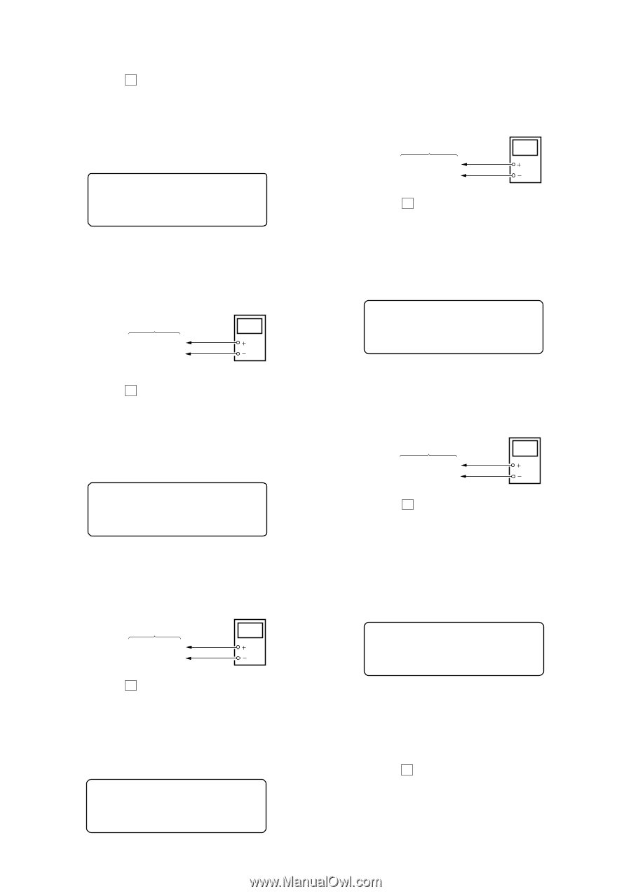
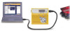
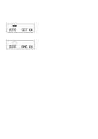
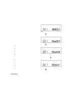
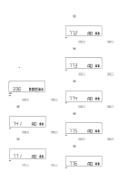
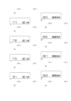
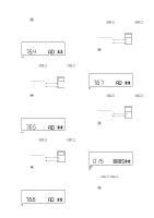
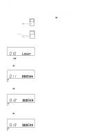
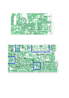
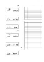
MZ-N505 2. Press the X key to write the adjusted value. Adjustment and Connection Location: MAIN board (See page 25) • Adjustment Method of Vl PWM Duty (L) (item number: 764) Set LCD display 764 **: Adjusted value AD ** 1. Connect a digital voltmeter to the AP913 (VLO) on the MAIN board, and adjust [VOL +] key (voltage up) or [VOL --] key (voltage down) so that the voltage becomes 2.30 ± 0.01 V. digital voltmeter MAIN board AP913 (VLO) AP602 (GND) 2. Press the X key to write the adjusted value. Adjustment and Connection Location: MAIN board (See page 25) • Adjustment Method of Vl PWM Duty (H) (item number: 765) Set LCD display 765 AD ** **: Adjusted value 1. Connect a digital voltmeter to the AP913 (VLO) on the MAIN board, and adjust [VOL +] key (voltage up) or [VOL --] key (voltage down) so that the voltage becomes 2.55 ± 0.01 V. digital voltmeter MAIN board AP913 (VLO) AP602 (GND) 2. Press the X key to write the adjusted value. Adjustment and Connection Location: MAIN board (See page 25) • Adjustment Method of Vrec PWM Duty (L) (item number: 766) Set LCD display 1. Connect a digital voltmeter to the TP (VREC) on the MAIN board, and adjust [VOL +] key (voltage up) or [VOL --] key (voltage down) so that the voltage becomes 1.13 ± 0.02 V. digital voltmeter MAIN board TP (VREC) AP602 (GND) 2. Press the X key to write the adjusted value. Adjustment and Connection Location: MAIN board (See page 25) • Adjustment Method of Vrec PWM Duty (H) (item number: 767) Set LCD display 767 **: Adjusted value AD ** 1. Connect a digital voltmeter to the TP (VREC) on the MAIN board, and adjust [VOL +] key (voltage up) or [VOL --] key (voltage down) so that the voltage becomes 1.65 to 1.75 V. digital voltmeter MAIN board TP (VREC) AP602 (GND) 2. Press the X key to write the adjusted value. Adjustment and Connection Location: MAIN board (See page 25) TEMPERATURE COREECTION • Adjustment Method of Temperature Correction 1. Select the manual mode of test mode, and set the item number 015 (see page 14). Set LCD display 015 ###: Address **: Adjusted value ###S** 2. Measure the ambient temperature. 3. Adjust with [VOL +], [VOL --] key so that the adjusted value (hexadecimal value) becomes the ambient temperature. (Initial value: 19h = 25 °C, Adjusting range: 80h to 7fh (-128 °C to +127 °C) 4. Press the X key to write the adjusted value. 766 **: Adjusted value AD ** 23
-
 1
1 -
2
-
3
-
4
-
5
-
6
-
7
-
8
-
9
-
10
-
11
-
12
-
13
-
14
-
15
-
16
-
17
-
 18
18 -
 19
19 -
 20
20 -
 21
21 -
 22
22 -
 23
23 -
 24
24 -
 25
25 -
 26
26 -
 27
27 -
 28
28 -
29
-
30
-
31
-
32
-
33
-
34
-
35
-
36
-
37
-
38
-
39
-
40
-
41
-
42
-
43
-
44
-
45
-
46
-
47
-
48
-
49
-
50
-
51
-
52
-
53
-
54
-
55
-
56
-
57
-
58
-
59
-
60
-
61
-
62
-
63
-
64
-
65
-
66
 |
 |