Sony PCWA-A200 Primary User Manual - Page 12
Parts and indicators
 |
View all Sony PCWA-A200 manuals
Add to My Manuals
Save this manual to your list of manuals |
Page 12 highlights
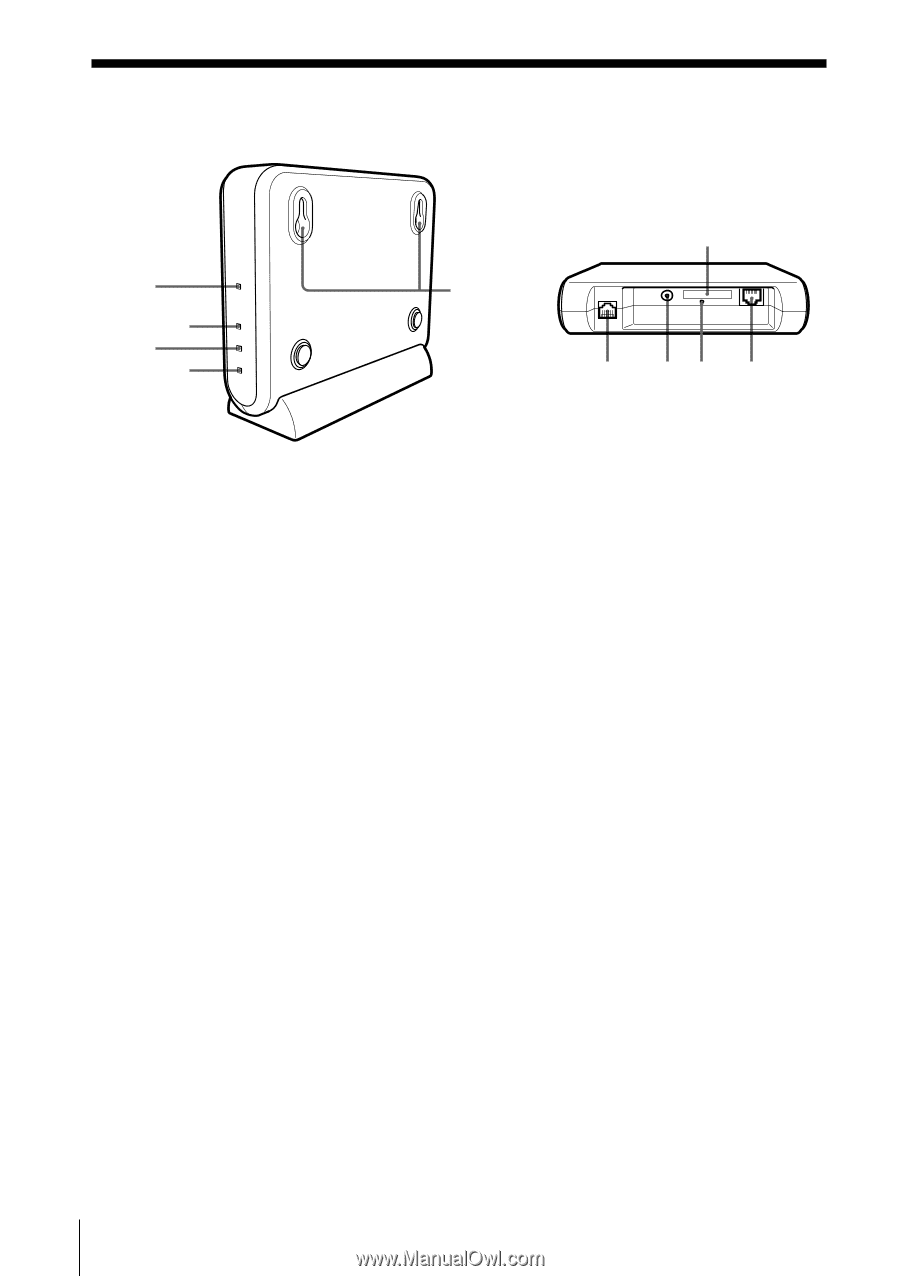
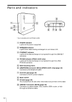
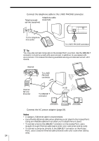
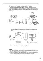
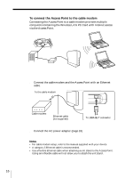
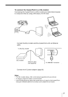
Parts and indicators 1 2 3 4* 5 9 LINE/ PHONE DC IN 5V 10BASE-T 6* 7 8 0 * Not included with the PCWA-A200. 1 POWER indicator Lights while power is supplied. 2 WIRELESS indicator Lights when data is being exchanged on a wireless LAN. 3 ETHERNET indicator Lights while data exchange is in progress through the 10BASE-T connector. 4 PHONE indicator (PCWA-A100 only) Lights while data exchange is in progress through the LINE/ PHONE connector. 5 Wall-mounting holes 6 LINE/PHONE connector (RJ-11) (PCWA-A100 only) (page 14) Connects to the telephone cable. 7 DC IN 9V jack (page 19) Connects to the AC power adapter. 8 Reset switch 9 ID label (page 20) The Access Point ID and other information are printed on this label. 0 10BASE-T connector (RJ-45) (page 15) Connects to a cable modem, DSL modem, ISDN router, or hub through an Ethernet cable. 12
-
 1
1 -
2
-
3
-
4
-
5
-
6
-
 7
7 -
 8
8 -
 9
9 -
 10
10 -
 11
11 -
 12
12 -
 13
13 -
 14
14 -
 15
15 -
 16
16 -
 17
17 -
18
-
19
-
20
-
21
-
22
-
23
-
24
-
25
-
26
-
27
-
28
-
29
-
30
-
31
-
32
 |
 |