Sony RDR-HX900 Quick Start Guide - Page 1
Sony RDR-HX900 Manual
 |
UPC - 027242644328
View all Sony RDR-HX900 manuals
Add to My Manuals
Save this manual to your list of manuals |
Page 1 highlights
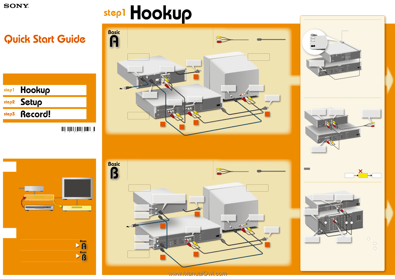
RDR-HX900 Follow the three steps below to connect, setup and make recordings on your DVD recorder. ©2004 Sony Corporation Printed in Malaysia 2-187-190-11(1) You have a: Cable Box with Video / Audio Output -or- Satellite Receiver Cable Box / Satellite Receiver to CABLE IN CAVLE IN ANT IN OUT TO TV to VIDEO OUT/ AUDIO OUT VIDEO OUT COMPONENT OUT DAIGUDITIAOL OUT OPTICAL S VIDEO to an AC outlet 4 to your wall jack to OUT TO TV DVD Recorder to LINE OUT to LINE IN 1 or 2 1 or 3 VHF/UHF IN SECTOTNOTPROBOL X COMPONENT VIDEO IN S VIDEO LINE IN R AUDIO L VIDEO 1 OUT G-LINK 3 CONTROL S IN LINE OUT Y PCMD/DIGTSI/TDAOLLBYODUIGTITAL COAXIAL 1 R AUDIO L VIDEO PB 2 S VIDEO PR OPTICAL CVOIDMEPOONOEUNTT Y PB PR 1 3 2 You will need: X2 (one audio/video cord is supplied) X3 (one coaxial cable is supplied) Television to VHF/UHF IN VHF/UHF IN LINE IN to LINE IN to an AC outlet 4 Connect all power cords last! Before hookup 1 Disconnect your VCR If you have been using a VCR, you do not need to disconnect all of your equipment. Just disconnect your VCR and connect the DVD recorder in its place. Television Cable Box / Satellite Receiver VCR DVD Recorder VCR 2 If you plan to use your VCR, reconnect it by following the instructions in "Connecting a VCR or similar device" on this page. Select a connection Select one of the following two types of basic connections according to the type of equipment you have. Cable Box with Video/Audio Output - or - Satellite Receiver Cable (cable box without video/audio output) - or - Antenna Proceed to Step 1 and begin! You have a: Cable (cable box without video / audio output) -or- Antenna Cable Box to RF IN to RF OUT If you don't have a cable box, connect this coaxial cable directly to VHF/UHF IN on the DVD Recorder. RF IN OUT to an AC outlet 4 to your wall jack to VHF/UHF IN to VHF/UHF OUT DVD Recorder 1 VHF/UHF IN SECTOTNOTPROBOL X COMPONENT VIDEO IN S VIDEO LINE IN R AUDIO L VIDEO 1 OUT G-LINK 3 CONTROL S IN to LINE OUT 1 or 2 LINE OUT Y PCMD/DIGTSI/TDAOLLBYODUIGTITAL COAXIAL 1 R AUDIO L VIDEO PB 2 S VIDEO CVOIDMEPOONOEUNTT Y PB PR PR OPTICAL 3 2 You will need: X1 (one audio/video cord is supplied) X3 (one coaxial cable is supplied) Television to VHF/UHF IN VHF/UHF IN LINE IN to LINE IN to an AC outlet 4 Connect all power cords last! Connecting the Set Top Box controller Place it so that the tip of the controller is directly above the remote control reception window on your set top box. VIDEO OUT COMPONENT OUT to SET TOP BOX CONTROL CAVLE IN ANT IN OUT TO TV DAIGUDITIAOL OUT OPTICAL S VIDEO VHF/UHF IN SECTOTNOTPROBOL X R COMPONENT VIDEO LINE IN AUDIO L VIDEO IN S VIDEO 1 OUT G-LINK 3 CONTROL S IN LINE OUT Y PCMD/DIGTSI/TDAOLLBYODUIGTITAL COAXIAL 1 R AUDIO L VIDEO PB 2 S VIDEO PR OPTICAL CVOIDMEPOONOEUNTT Y PB PR Cable Box / Satellite Receiver DVD Recorder You can have the recorder change the channel of your cable box or satellite receiver to the channel you want to record, just before the timer recording starts. Connect the Set Top Box controller(supplied), and select "Yes" in step 9 of Setup on the next page. Connecting a VCR or similar device to LINE OUT 1 to LINE OUT 2 VCR to any unused LINE IN jack on your TV S VIDEO VHF/UHF IN SECTOTNOTPROBOL X COMPONENT VIDEO IN S VIDEO LINE IN R AUDIO L VIDEO 1 OUT G-LINK 3 CONTROL S IN LINE OUT Y PCMD/DIGTSI/TDAOLLBYODUIGTITAL 1 R AUDIO L COAXIAL VIDEO PB 2 S VIDEO PR OPTICAL CVOIDMEPOONOEUNTT Y PB PR DVD Recorder to LINE IN 3 To record your video tapes to a DVD, connect an audio/video cable (not supplied) to the LINE OUT 1 jacks on your VCR to the LINE 3 IN jacks on the recorder. To just watch your video tapes, connect your VCR's LINE OUT 2 jacks directly to any unused LINE IN jack on your TV. NOTE Do not connect your VCR between this DVD recorder and your TV. If you do not first connect your VCR to the recorder, you will be unable to watch DVD Recorder VCR TV pictures from your recorder. Connecting an AV amplifier (receiver) to DIGITAL OUT to LINE OUT (COAXIAL or OPTICAL) (R-AUDIO-L) 1 or 2 to DIGITAL IN (OPTICAL) VHF/UHF IN SECTOTNOTPROBOL X COMPONENT VIDEO IN S VIDEO LINE IN R AUDIO L VIDEO 1 OUT G-LINK 3 CONTROL S IN LINE OUT YY PCMD/DIGTSI/TDAOLLBYODUIGTITAL COAXIAL 1 R AUDIO L VIDEO PB 2 S VIDEO PR OPTICAL CVOIDMEPOONOEUNTT Y PB PR DIGITAL IN c ba DVD Recorder AV Amplifier to DIGITAL IN (COAXIAL) LINE IN to LINE IN (AUDIO) Connect one of the following cords (not supplid) audio cords a -or- coaxial digital cord b -or- optical digital cord c Connecting to an AV amplifier (receiver) with audio cords will enable you to enjoy the TVS surround effects of this recorder, while connecting with digital cords will enable you to listen to Dolby Digital or DTS surround effects. For further explanations, see "Connecting the Audio Cords" in the Operating Instructions.
-
 1
1 -
 2
2
 |
 |