Sony STR-DE475 Service Manual
Sony STR-DE475 - Fm Stereo/fm-am Receiver Manual
 |
View all Sony STR-DE475 manuals
Add to My Manuals
Save this manual to your list of manuals |
Sony STR-DE475 manual content summary:
- Sony STR-DE475 | Service Manual - Page 1
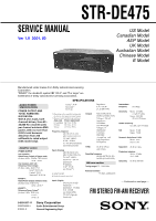
SERVICE MANUAL Ver 1.0 2001. 02 STR-DE475 US Model Canadian Model AEP Model UK Model Australian Model Chinese Model E Model Manufactured under license from Dolby Laboratories Licensing Corporation. "DOLBY" the double-D symbol ; "AC-3" and "Pro Logic" are trademarks of Dolby Laboratories Licensing - Sony STR-DE475 | Service Manual - Page 2
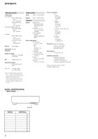
165 W In Standby Condition: 1 W Dimensions 430 × 145 × 298 mm (17 × 7 7/8 × 19 5/8 in.) including projecting parts and controls Mass (Approx.) 7.2 kg (15 lb 14 oz) Supplied accessories • FM wire antenna (1) • AM loop antenna (1) • R6 (size-AA) batteries (2) • Remote Commander (remote) (1) Design and - Sony STR-DE475 | Service Manual - Page 3
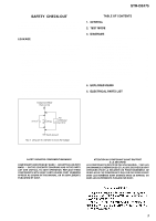
STR-DE475 SAFETY CHECK-OUT After correcting the original service problem, perform the following safety checks before releasing the set to the customer: Check the antenna terminals, metal trim, "metallized" knobs, screws, and all other exposed metal parts for AC leakage. Check leakage as described - Sony STR-DE475 | Service Manual - Page 4
STR-DE475 SECTION 1 GENERAL This section is extracted from instruction manual. 4 - Sony STR-DE475 | Service Manual - Page 5
STR-DE475 5 - Sony STR-DE475 | Service Manual - Page 6
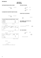
Digital Cinema Sound, SET UP and 2CH LED turn on. 3. Press the VIDEO button, confirm display DIGITAL DTS SP.OFF OPT MULTI CH IN C ((( ))) SL SR MONO EQ NEWS MEMORY dB Hz ft. MULTI CHANNEL can be used.) FACTORY SET MODE * All preset contents are reset to the default setting. * Procedure: - Sony STR-DE475 | Service Manual - Page 7
STR-DE475 . Replace only with part number specified. Note: FM f : CD • Abbreviation CND : Canadian model. AUS : Australian model. AR : Argentine model. CH : Chinese model. MX : Mexican model. • Waveform - MAIN BOARD - 1 IC301 qf 230ns 2.2Vp-p - DISPLAY BOARD - 2 IC102 id 63ns 5.8Vp-p - DIGITAL - Sony STR-DE475 | Service Manual - Page 8
STR-DE475 3-1. CIRCUIT BOARDS LOCATION STANDBY board POWER SW board HP board AC SELECT board VIDEO board DIGITAL board DISPLAY board MAIN board 8 - Sony STR-DE475 | Service Manual - Page 9
59 AEP, UK MODEL 44 STEREO AUTO STOP T MUTING TUNER DATA IN TUNER DATA OUT TUNER CLK TUNER LAT RDS SIGNAL 12 V1 S1 2 S2 13 M2 4 5 OUT M1 11 3 V2 75 S1 76 S2 74 VIDEO MUTING 1 V3 53 48 RDS CLK RDS DATA IC1003 IC1003 3 56 2 DIGITAL AUDIO I/F RECEIVER IC1004 3 DIN0 MCLK - Sony STR-DE475 | Service Manual - Page 10
STR-DE475 3-3. BLOCK DIAGRAM - DISPLAY SECTION - • R-CH is omitted due to same as L-CH. • Signal Path : FM L SIRCS 57 IC101 REMOTE 1 CONTROL 2 RECEIVER D109 VCC 23 VCC 84 RESET 77 HSTX 52 STOP 47 8 D101 B RESET D110 RESET Q100,101 POWER RY POWER AMP -B FL201 -30V TUNER +12V RELAY +B AUDIO + - Sony STR-DE475 | Service Manual - Page 11
3-4. SCHEMATIC DIAGRAM - MAIN SECTION (1/3) - • See page 21 for IC Block Diagram. STR-DE475 IC B/D IC B/D IC B/D 11 11 - Sony STR-DE475 | Service Manual - Page 12
STR-DE475 3-5. SCHEMATIC DIAGRAM - MAIN SECTION (2/3) - • See page 21 for IC Block Diagram. 15 19 15 17 1 IC B/D IC B/D 17 17 12 12 - Sony STR-DE475 | Service Manual - Page 13
STR-DE475 3-6. SCHEMATIC DIAGRAM - MAIN SECTION (3/3) - 17 13 13 - Sony STR-DE475 | Service Manual - Page 14
3-7. PRINTED WIRING BOARD - MAIN SECTION - • See page 8 for Circuit Boards Location. STR-DE475 There are a few cases that the part printed on this diagram isn't mounted in this model. TUNER UNIT IC 301 IC 404 IC 402 IC 403 IC 201 IC 501 IC 701 IC 401 IC 803 IC 801 IC 802 IC - Sony STR-DE475 | Service Manual - Page 15
STR-DE475 3-8. SCHEMATIC DIAGRAM - DIGITAL SECTION - • See page 21 for IC Block Diagram. • See page 7 for Waveforms. IC B/D 17 IC B/D 15 15 - Sony STR-DE475 | Service Manual - Page 16
SECTION - • See page 8 for Circuit Boards Location. DIGITAL (Page 18) IC 1002 IC 1010 IC 1009 IC 1013 (Page 14) IC 1003 STR-DE475 There are a few cases that the part printed on this diagram isn't mounted in this model. IC 1004 IC 1005 IC 1006 IC 1011 • Semiconductor Location Ref - Sony STR-DE475 | Service Manual - Page 17
STR-DE475 3-10. SCHEMATIC DIAGRAM - DISPLAY SECTION - • See page 23 for IC Pin Function. • See page 7 for Waveforms. 13 15 19 17 17 - Sony STR-DE475 | Service Manual - Page 18
D102 A-8 D103 C-6 D109 B-12 D110 B-12 IC101 B-13 IC102 B-7 IC103 B-10 Q008 D-12 Q009 C-5 Q100 A-8 Q101 A-7 Q103 D-3 Q104 D-3 18 18 STR-DE475 There are a few cases that the part printed on this diagram isn't mounted in this model. (Page 20) (Page 14) IC 101 (Page 14) - Sony STR-DE475 | Service Manual - Page 19
STR-DE475 3-12. SCHEMATIC DIAGRAM - VIDEO SECTION - • See page 21 for IC Block Diagram. • See page 13 for Printed Wiring Board. IC B/D 17 19 19 - Sony STR-DE475 | Service Manual - Page 20
(Page 14) (Page 14) IC 950 (Page 18) STR-DE475 3-14. PRINTED WIRING BOARD - VIDEO SECTION -• See page 8 for Circuit Boards Location. • See page 20 for Schematic Diagram. There are a few cases that the part printed on this diagram isn't mounted in this model. IC 1015 IC 1014 (Page 18) (Page 14 - Sony STR-DE475 | Service Manual - Page 21
3-15. IC BLOCK DIAGRAMS IC1015 NJM2279D (VIDEO BOARD) STR-DE475 IC1008 AK4527 (DIGITAL BOARD) VSW2 VIN1 MUTE1 VOUT1 NC V+ LOOP1 LOOP0/SDA/ 32 RIN+ 31 RIN- 30 LIN+ 29 LIN- 28 ROUT1 27 LOUT1 26 ROUT2 25 LOUT2 24 ROUT3 23 LOUT3 DEM1 DEM0 TVDD DVDD DVSS PDN ICKS2 ICKS1 ICKS0 CAD1 CAD0 XO XI VDD2 VSS2 - Sony STR-DE475 | Service Manual - Page 22
STR-DE475 IC950 NJM2103D (STANDBY BOARD) IC1004 LC89055W-RA8 (DIGITAL BOARD) CR 1 VSC 2 +- OUTC 3 GND 4 VREF Q RS 8 RESET -+ 7 VSA 6 VSB/SESIN 5 V+ +- +- DISEL 1 DOUT 2 DIN0 3 DIN1 4 DIN2 5 DGND 6 DVDD 7 R8 VIN 9 LPF 10 AVDD 11 AGND 12 CKOUT 13 BCK 14 DGND 15 DATAO - Sony STR-DE475 | Service Manual - Page 23
DT MD0 MD1 I/O I Read volume encoder A changing I Read volume encoder B changing O Control Blue LED O Control DCS LED O Control AFD LED O Control 2CH LED O Control MODE LED O Control power relay - O Control front speaker relay - Ground O Control center speaker relay O Control woofer relay O Control - Sony STR-DE475 | Service Manual - Page 24
I 97 P14 - 98 ANG/DIG O 99 Y_CSB O 100 Y_IC O Selection of micom operation mode Hardware standby signal Read RDS clock Detect headphone switch Detect power switch key Input data from remote control receiver Detect protector status Output latch signal to tuner Output data signal to tuner - Sony STR-DE475 | Service Manual - Page 25
supplied. • Accessories and packing materials are given in the last of this parts list. • Abbreviation CND: Canadian model. AUS : Australian model. AR : Argentine model. CH : Chinese model. MX : Mexican model. 6 STR-DE475 The components identified by mark 0 or dotted line with mark 0 are critical - Sony STR-DE475 | Service Manual - Page 26
STR-DE475 #2 not supplied 67 66 71 #1 63 #1 55 #3 #3 not supplied T901 not supplied 70 69 not 56 57 57 57 57 57 58 60 61 61 62 62 62 62 62 62 62 62 Part No. Description Remarks A-2007-946-A DIGITAL BOARD, COMPLETE 4-232-237-01 FOOT (DIA. 30) A-2007-945-A STANDBY BOARD, COMPLETE (US - Sony STR-DE475 | Service Manual - Page 27
SECTION 5 ELECTRICAL PARTS LIST STR-DE475 AC SELECT DIGITAL NOTE: • Due to standardization, replacements in the parts list may be different from the parts specified in the diagrams or the components used on the set. • -XX, -X mean standardized parts, so they may have some difference from the - Sony STR-DE475 | Service Manual - Page 28
STR-DE475 DIGITAL DISPLAY Ref. No. Part No. Description < DIODE > D1101 D1201 D1202 D1301 8-719-016- 0UH FB1305 1-414-813-11 FERRITE 0UH < IC > IC1002 IC1003 IC1004 IC1005 IC1006 8-749-923-05 TORX178B(OPTICAL(TV/SAT IN)) 8-759-242-70 IC TC7WU04F(TE12R) 8-759-639-35 IC LC89055W-RA8 8-759-242- - Sony STR-DE475 | Service Manual - Page 29
STR-DE475 DISPLAY Ref. No. C104 C105 C106 C107 C108 Part No. Description 1-127-880-31 CERAMIC 1-127-880-31 CERAMIC 1-127-880-31 CERAMIC 1-127-880-31 CERAMIC 1-127-880-31 CERAMIC 0.022uF 10% 0.022uF 10% 0.022uF 10% 0.022uF 10% 0.022uF 10% Remarks 50V 50V 50V 50V 50V Ref. No. FB100 Part No. - Sony STR-DE475 | Service Manual - Page 30
STR-DE475 DISPLAY Ref. No. R058 R062 R064 R065 R098 Part No. Description 1-247-807-31 CARBON 1-249- SWITCH, TACTILE (EXEPT AEP,UK:AM)(AEP,UK:FM/AM) 1-762-875-21 SWITCH, TACTILE (EXEPT AEP,UK:FM)(AEP,UK:FM MODE) 1-762-875-21 SWITCH, TACTILE (EXEPT AEP,UK:FM MODE)(AEP,UK:PTY) 1-762-875-21 SWITCH, - Sony STR-DE475 | Service Manual - Page 31
STR-DE475 DISPLAY HP MAIN Ref. No. S128 S129 S130 S131 S132 Part No. Description 1-762-875-21 SWITCH, TACTILE (VIDEO) 1-762-875-21 SWITCH, TACTILE (MD/TAPE) 1-762-875-21 SWITCH, TACTILE (MODE) 1-762-875-21 SWITCH, TACTILE (MUTING) 1-762-875-21 SWITCH, TACTILE (MULTI CH IN) Remarks Ref. No. C308 - Sony STR-DE475 | Service Manual - Page 32
STR-DE475 MAIN Ref. No. C462 C463 C464 C465 C466 Part No. Description 1-130-481-00 MYLAR components identified by mark ! or dotted line with mark ! are critical for safety. Replace only with part number specified. Les composants identifiés par une marque ! sont critiques pour la sécurité. Ne les - Sony STR-DE475 | Service Manual - Page 33
STR-DE475 MAIN Ref. No. CC03 Part No. Description 1-128-809-11 CERAMIC CC04 1-128 components identified by mark ! or dotted line with mark ! are critical for safety. Replace only with part number specified. Les composants identifiés par une marque ! sont critiques pour la sécurité. Ne les - Sony STR-DE475 | Service Manual - Page 34
STR-DE475 MAIN Ref. No. IC404 IC501 IC701 IC702 IC801 Part No. Description 8-759-636-74 IC M5218AP-22 8-749-011-16 IC STK350-230 8-759-326-52 IC uPC2581V 8-759-326-52 IC uPC2581V 8-759-605-00 IC M5F78M07L Remarks Ref. No. Q657 Q658 Q659 Q691 Q692 Part No. Description 8-729-900-63 TRANSISTOR - Sony STR-DE475 | Service Manual - Page 35
11 CARBON 1-249-429-11 CARBON 1-249-437-11 CARBON 1-249-437-11 CARBON STR-DE475 MAIN 47K 47K 100 100 100 100 100 100 10K 100K 10K 1K 1K 1K 1K 1K 1K 1K 1K 1K 1K 1K 1K 47K 47K 47K 10K 47K 47K Remarks Ref. No. Part No. Description Remarks 5% 1/4W 5% 1/4W 5% 1/4W 5% 1/4W 5% 1/4W R469 R470 R471 - Sony STR-DE475 | Service Manual - Page 36
STR-DE475 MAIN Ref. No. R539 R540 R541 R573 R601 R602 R603 R604 R610 R611 EXCEPT US,CND) R745 R746 R747 R748 R751 R752 R753 R754 R760 R761 R763 0 R764 0 R765 0 R766 0 R767 0 R768 Part No. Description 1-215-888-00 METAL OXIDE 220 1-216-453-00 METAL OXIDE 270 1-249-417-11 CARBON 1K 1-249-439- - Sony STR-DE475 | Service Manual - Page 37
STR-DE475 MAIN POWER SW STANDBY Ref. No. Part No. Description R770 1-249-425-11 CARBON 4.7K 1uF 50V RY550 RY560 RY601 RY730 RY791 1-755-170-11 RELAY (12V) 1-755-267-11 RELAY 1-755-170-11 RELAY (12V) 1-755-170-11 RELAY (12V) 1-515-614-11 RELAY < CONNECTOR > CNP901 1-564-321-00 PIN, CONNECTOR - Sony STR-DE475 | Service Manual - Page 38
STR-DE475 STANDBY VIDEO Ref. No. D914 D914 D915 D915 0 F901 0 F901 Part No. Description Remarks 8- 1-249-417-11 CARBON 1-249-431-11 CARBON 1K 5% 1/4W F 15K 5% 1/4W < RELAY > 1-755-298-11 RELAY 1-755-276-11 RELAY, POWER (AEP,UK,AUS,CH,AR) R1601 1-247-804-11 CARBON 75 5% 1/4W R1602 1- - Sony STR-DE475 | Service Manual - Page 39
Ref. No. Part No. Description Remarks ACCESSORIES & PACKING MATERIALS 1-476-552-11 REMOTE COMMANDER (RM-U305) 1-501-374-11 ANTENNA, LOOP (AM) 1-501-594-11 ANTENNA (FM) (AEP,UK,AUS,CH) 1-793-184-21 CONNECTOR (F TYPE ADAPTOR) (US,CND,E,MX,BR,AR) 4-233-503-11 INSTRUCTION MANUAL (US,CND,AUS,CH)( - Sony STR-DE475 | Service Manual - Page 40
STR-DE475 REVISION HISTORY Clicking the version allows you to jump to the revised page. Also, clicking the version at the upper right on the revised page allows you to jump to the next revised page. Ver. Date 1.0 2001.02 New Description of Revision
-
 1
1 -
 2
2 -
 3
3 -
 4
4 -
 5
5 -
 6
6 -
 7
7 -
8
-
9
-
10
-
11
-
12
-
13
-
14
-
15
-
16
-
17
-
18
-
19
-
20
-
21
-
22
-
23
-
24
-
25
-
26
-
27
-
28
-
29
-
30
-
31
-
32
-
33
-
34
-
35
-
36
-
37
-
38
-
39
-
40
 |
 |
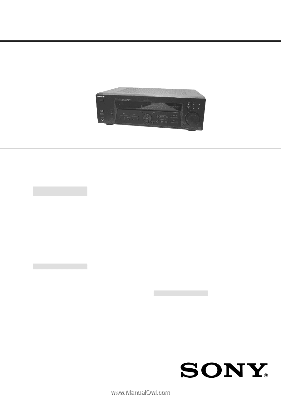
STR-DE475
US Model
Canadian Model
AEP Model
UK Model
Australian Model
Chinese Model
E Model
SERVICE MANUAL
FM STEREO FM-AM RECEIVER
Sony Corporation
Audio Entertainment Group
General Engineering Dept.
9-929-587-11
2001B1600-1
© 2001.2
— Continued on next page —
SPECIFICATIONS
Ver 1.0
2001. 02
Manufactured under license from Dolby Laboratories Licensing
Corporation.
“DOLBY” the double-D symbol
;
“AC-3” and “Pro Logic” are
trademarks of Dolby Laboratories Licensing Corporation.
Outputs
MD/TAPE (OUT):
VIDEO (AUDIO OUT):
Voltages:
250 mV,
Impedance:
10 kilohms
SUB WOOFER:
Voltage: 2 V
Impedance :
1 kilohms
PHONES:
Accepts low– and
high-impedance
headphones
TONE
±
6 dB at 100 Hz
and 10 kHz
Sampling frequency
48 kHz (OPTICAL IN)
96 kHz (COAXIAL IN)
FM tuner section
Tuning range
87.5 - 108.0 MHz
Antenna terminals
75 ohms, unbalanced
Intermediate
frequency
10.7 MHz
Sensitivity
Mono:
18.3 dBf,
2.2
µ
V/75 ohms
Stereo:
38.3 dBf,
22.5
µ
V/75 ohms
Usable sensitivity
11.2 dBf, 1
µ
V/75 ohms
S/N
Mono:
76 dB
Stereo:
70 dB
Harmonic distortion at 1 kHz
Mono:
0.3%
Stereo: 0.5%
Separation
45 dB at 1 kHz
Frequency response
30 Hz - 15 kHz
+0.5/-2 dB
Selectivity
60 dB at 400 kHz
AUDIO POWER
SPECIFICATIONS
POWER OUTPUT AND
TOTAL HARMONIC
DISTORTION:
With 8 ohm loads, both
channels driven, from 40 -
20,000 Hz; rated 80 watts
per channel minimum RMS
power, with no more than
0.09% total harmonic
distortion from 250
milliwatts to rated output
(USA model only).
Amplifier section
POWER OUTPUT
US, Canadian :
Rated Power Output at Stereo mode
(8 ohms 40 Hz - 20 kHz, THD 0.09%)
80 W + 80 W
US, Canadian, AEP, UK :
Reference Power Output
(8 ohms 1 kHz, THD 0.7%)
Front
1)
: 80 W/ch
Center
1)
: 80 W
Surround
1)
: 80 W/ch
EXCEPT :
EXCEPT :
Rated Power Output at Stereo mode
(8 ohms 1kHz, THD 0.7%)
80 W + 80 W
2)
Reference Power Output
2)
(8 ohms 1 kHz, THD 10%)
Front
1)
:
90 W/ch
Center
1)
: 90 W
Surround
1)
:
90 W/ch
1) Depending on the sound field settings and
the sources, there may be no sound output.
2) Measured under the following conditions:
Area code
Power requirement
E, Australian
240 V AC, 50 Hz
Chinese
230 V AC, 50 Hz
Taiwan
110 V AC, 50 Hz
Frequency response
MULTI CH IN, CD,
MD/TAPE, DVD/LD,
TV/SAT, VIDEO:
20 Hz – 20 kHz
0/– 0.5 dB (sound field,
and tone bypassed)
Inputs (Analog)
MULTI CH IN, CD,
MD/TAPE, DVD/LD,
TV/SAT, VIDEO:
Sensitivity:
250 mV
Impedance:
50 kilohms
S/N
3)
:
85 dB
(A, 250 mV
4)
)
3) INPUT SHORT
4) Weighted network, input level
Inputs (Digital)
DVD/LD (coaxial):
Sensitivity:
–
Impedance:
75 ohms
S/N:
100 dB
(A, 20 kHz LPF)
TV/SAT (Optical):
Sensitivity:
–
Impedance:
–
S/N:
100 dB
(A, 20 kHz LPF)