Sony STR-K990 Operating Instructions - Page 23
Connecting a TV, Getting Started, Notes
 |
View all Sony STR-K990 manuals
Add to My Manuals
Save this manual to your list of manuals |
Page 23 highlights
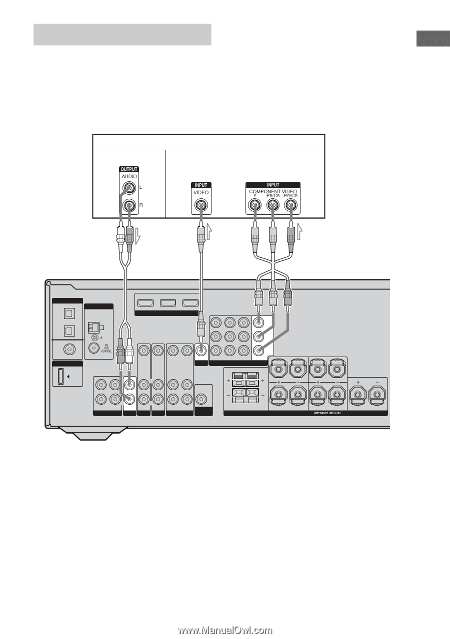
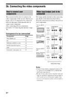
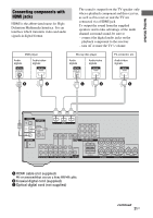
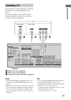
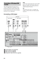
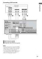
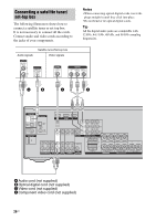
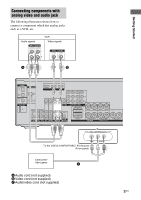
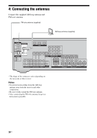
Getting Started Connecting a TV The image from a visual component connected to this receiver can be displayed on a TV screen. It is not necessary to connect all the cords. Connect audio and video cords according to the jacks of your components. Audio signals TV Video signals A B C DIGITAL OPTICAL SAT IN ANTENNA VIDEO 2/ AM BD IN COAXIAL DVD IN DMPORT DVD IN VIDEO 2/BD IN OUT HDMI Y PB/CB PR/CR VIDEO IN VIDEO IN VIDEO OUT VIDEO IN VIDEO OUT SAT IN DVD IN VIDEO 1 IN MONITOR OUT L MONITOR COMPONENT VIDEO RL L L L L AUDIO OUT R R OUT IN IN SA-CD/CD/CD-R TV R R AUDIO IN AUDIO IN AUDIO OUT AUDIO IN SUB SAT DVD VIDEO 1 WOOFER FRONT B R FRONT A SPEAKERS L R SURROUND CENTER A Audio cord (not supplied) B Video cord (not supplied) C Component video cord (not supplied) Notes • Connect image display components such as a TV or a projector to the MONITOR OUT jack on the receiver. • Be sure to turn on the receiver when the video and audio of a playback component are being output to a TV via the receiver. If the power supply of the receiver is not turned on, neither video nor audio is transmitted. Tips • You can watch the selected input image when you connect the MONITOR OUT jack to a TV. • To output the sound of the TV from the speakers connected to the receiver, be sure to - connect the audio output jacks of the TV to the TV IN jacks of the receiver. - turn off or mute the TV's volume. 23US
-
 1
1 -
2
-
3
-
4
-
5
-
6
-
7
-
8
-
9
-
10
-
11
-
12
-
13
-
14
-
15
-
16
-
17
-
 18
18 -
 19
19 -
 20
20 -
 21
21 -
 22
22 -
 23
23 -
 24
24 -
 25
25 -
 26
26 -
 27
27 -
 28
28 -
29
-
30
-
31
-
32
-
33
-
34
-
35
-
36
-
37
-
38
-
39
-
40
-
41
-
42
-
43
-
44
-
45
-
46
-
47
-
48
-
49
-
50
-
51
-
52
-
53
-
54
-
55
-
56
-
57
-
58
-
59
-
60
-
61
-
62
-
63
-
64
-
65
-
66
-
67
-
68
-
69
-
70
-
71
-
72
-
73
-
74
-
75
-
76
-
77
-
78
-
79
-
80
 |
 |