Sony UP-DP10 Operating Instructions / Mode d’emploi - Page 36
Parallel Interface Connector Pin, Assignments, USB Interface, Complies with Universal Serial Bus
 |
View all Sony UP-DP10 manuals
Add to My Manuals
Save this manual to your list of manuals |
Page 36 highlights
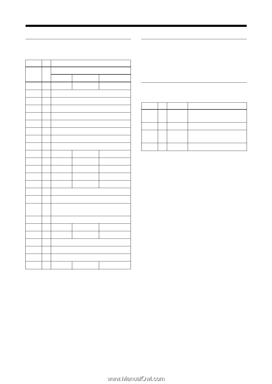
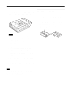
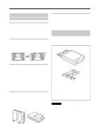
Miscellaneous Parallel Interface Connector Pin Assignments Pin No. I/O Signal Interface mode Compatible Nibble ECP 1 I nStrobe HostClk HostClk 2 I/O Data1 (LSB) 3 I/O Data2 4 I/O Data3 5 I/O Data4 6 I/O Data5 7 I/O Data6 8 I/O Data7 9 I/O Data8 (MSB) 10 O nACK PtrClk PeriphClk 11 O Busy PtrBusy PeriphAck 12 O PError AckDataReq nAckReverse 13 O Select Xflag Xflag 14 I nAutoFd HostBusy HostAck 15 Not defined 16-17 GND 18 O Peripheral Logic High (pull up to +5V with 1k Ω) 19-30 GND 31 I nInit nInit nReverseRequest 32 O nFault nDataAvail nPeriphRequest 33 Not defined 34 Not defined 35 Not defined 36 I nSelectln IEEE 1284 Active IEEE 1284 Active USB Interface Data transfer method Complies with Universal Serial Bus Specification Revision 1.0 USB Interface Connector Pin Assignments Pin No. I/O Signal VCC I/O -Data I/O +Data Ground Function Cable power, maximum current Data Data, pull up to +3.3V by a 1.5 Ω resistor Cable ground The specifications and appearance of this printer are subject to change without notice. Within the bi-directional parallel interface (IEEE STD 1284-1994) standard, the UP-DP10 supports Compatible mode, Reverse Nibble mode, and ECP mode. 36
-
 1
1 -
2
-
3
-
4
-
5
-
6
-
7
-
8
-
9
-
10
-
11
-
12
-
13
-
14
-
15
-
16
-
17
-
18
-
19
-
20
-
21
-
22
-
23
-
24
-
25
-
26
-
27
-
28
-
29
-
30
-
 31
31 -
 32
32 -
 33
33 -
 34
34 -
 35
35 -
 36
36 -
 37
37 -
 38
38 -
 39
39 -
 40
40 -
 41
41 -
42
-
43
-
44
-
45
-
46
-
47
-
48
-
49
-
50
-
51
-
52
-
53
-
54
-
55
-
56
-
57
-
58
-
59
-
60
-
61
-
62
-
63
-
64
-
65
-
66
-
67
-
68
-
69
-
70
-
71
-
72
 |
 |