Sony UP895 Service Manual
Sony UP895 - UP 895 B/W Dye Sublimation Printer Manual
 |
View all Sony UP895 manuals
Add to My Manuals
Save this manual to your list of manuals |
Sony UP895 manual content summary:
- Sony UP895 | Service Manual - Page 1
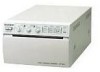
VIDEO GRAPHIC PRINTER UP-895 UP-895CE UP-895MD SERVICE MANUAL 1st Edition - Sony UP895 | Service Manual - Page 2
manual is intended for qualified service personnel only. To reduce the risk of electric shock, fire or injury, do not perform any servicing other than that contained in the operating instructions unless you are qualified to do so. Refer all servicing to qualified service étente uniquement. UP-895/(E) - Sony UP895 | Service Manual - Page 3
Table of Contents 1. Operating Instructions 2. Service Information 2-1. Board Layout 2-1 2-2. Disassembly 2-1 2-3. Removal of Major Parts 3. Electrical Alignment 3-1. AGC Adjustment 3-1 3-2. Video Level Adjustment 3-1 3-3. Brightness and Contrast Adjustment One-Line Memory 4-5 UP-895/(E) 1 - Sony UP895 | Service Manual - Page 4
Basic Operation 4-15 4-5-3. Stair Generation 4-15 4-5-4. Temperature Correction 4-16 4-5-5. Line Count Correction 4-16 5. Troubleshooting 5-1. Print is Faulty 5-1 5-2. Print is Too Dark or Too Light 5-2 5-3. "Paper Sensor" is Out of Order 5-3 5-4. Head Operation (Up & Down) is Out of Order - Sony UP895 | Service Manual - Page 5
8. Spare Parts 8-1. Notes on Repair Parts 8-1 8-2. Exploded Views 8-2 8-3. Electrical Parts List 8-7 9. Block Diagram Overall ...9-1 10. Schematic Diagrams and Board Layouts FRAME ...10-2 KY-454 ...10-2 SE-531 ...10-2 SE-532 ...10-2 SU-52 ...10-2 MA-99 ...10-4 UP-895/(E) 3 - Sony UP895 | Service Manual - Page 6
- Sony UP895 | Service Manual - Page 7
UP-895/(E) 3-868-286-01 (1) Video Graphic Printer Instructions for Use Page 20 GB Section 1 Operating Instructions This section is extracted from operation manual. (For UP-895MD/895CE) UP-895 UP-895MD UP-895CE © 1999 Sony Corporation 1-1 - Sony UP895 | Service Manual - Page 8
31 Specifications 32 Troubleshooting 34 Location and Function of Parts 35 Front 35 Back 36 Overview Introduction The UP-895/895MD/895CE is a black and white video graphics printer that can be used to print images displayed on a video monitor. This manual covers the UP-895/895MD/895CE - Sony UP895 | Service Manual - Page 9
last. Video equipment to video output connector Color/black and white video monitor Setting Up the Printer You can set the printer to the desired specifications using two kinds of switches. • Slide switches on the paper tray inside the front door You can easily set the printer specifications most - Sony UP895 | Service Manual - Page 10
to ON, and the other to OFF. When you connect the printer and a video monitor to the video equipment, set the 75Ω switch to OFF. Paper Use only UPP-110S/110HD/110HG paper as specified for the UP-895/895MD/895CE. If another type of paper is used, the quality of the printout cannot be guaranteed. Use - Sony UP895 | Service Manual - Page 11
the slide switches and DIP switches set correctly? (pages 22 and 23) • Is the paper type set correctly? (page 23) • Is the paper roll loaded properly? (page 26) • Is the video source being input? Making Printouts 1 Press the power switch to turn on the printer. The power lamp lights and the EMPTY - Sony UP895 | Service Manual - Page 12
printer and the printer will video monitor, set the set the selector to SIDE. STD SIDE STD SIDE Image displayed on the video monitor Printouts When set to the STD position When set of settings of setting video image on the monitor after it has been enlarged twice. Operation - Sony UP895 | Service Manual - Page 13
video signal is directly input to the video monitor without being processed by the printer when the setting is THRU, you can monitor the video signal as it is input directly from the video the unit only with a power source specified in "Specifications". • Stop operation immediately if any liquid or - Sony UP895 | Service Manual - Page 14
PRINT BUSY (TTL) Goes HIGH during printing. Supplied accessories Paper roll (UPP-110HG) (1) BNC y BNC connecting cable (1) AC power cord (1) Head cleaning sheet (1) Media label (1) The following specifications are applied only to the UP-895MD/895CE models: Storage and transport temperature -20°C to - Sony UP895 | Service Manual - Page 15
UP-895/(E) Others Troubleshooting Troubleshooting The following troubleshooting checks will help you correct the most common problems you may encounter with your printer. Before proceeding with these trouble check, first checks that the power cord is firmly connected. Should the problem persist - Sony UP895 | Service Manual - Page 16
Selects the line density. For detailed information on slide switches, see "Setting the Slide Switches on the Paper Tray" on page 22. qs Paper feeder and cutter Cuts the printing paper. Back 1 Equipotential terminal (only for UP-895MD/ 895CE) Used to connect to the equipotential plug to bring the - Sony UP895 | Service Manual - Page 17
Section 2 Service Information 2-1. Board Layout SE-532 board MA-99 board 2-2. Disassembly n Remove the top cover in the order shown in the figure during removal. Removal of Top Cover 2 Top cover 1 M3 case fixing screw KY-454 board SU-52 board SE-531 board 1 M3 case fixing screw UP-895/(E) - Sony UP895 | Service Manual - Page 18
(BVTT 3x6) 3 Claws 3 Claws 4 Front panel 2 Screws (BVTT 3x6) 2 Screws (BVTT 3x6) Be careful not to slacken the harness when installing the mechanical block. 2-2 UP-895/(E) - Sony UP895 | Service Manual - Page 19
(M3) 4 CN14 4 CN2 4 CN8 4 CN12 4 CN1 5 Tapping screws (M3) 4 CN13 4 CN7 4 CN3 6 MA-99 board 4 CN9 6 Switching regulator 4 Screws (PS 3x6) 4 Screws (PS 3x6) UP-895/(E) 2-3 - Sony UP895 | Service Manual - Page 20
(BVTT 3x6) 4 CN13 4 CN9 2 Screws (PSW 3x6) 3 Heat sink 1 Flat type wire (26 core) Printing side Contact 4 Thermal head 1 Flat type wire (30 core) 2-4 UP-895/(E) - Sony UP895 | Service Manual - Page 21
careful not to hold the gear bracket by hand when installing screws 1 and 2. 2. Confirm that the belt tension is not loosened after screw installation. UP-895/(E) 2-5 - Sony UP895 | Service Manual - Page 22
2-5. Installation of Fan Motor n Install the fan motor while paying the attention to the direction of the harness with the surface, to which the fan motor sticker is attached, down. Screws (PTT 3x10) Fan motor MA-99 board Top chassis CN6 2-6 UP-895/(E) - Sony UP895 | Service Manual - Page 23
ON and 75 Z terminator is off. 1RV3 1RV2 TP5 3-2. Video Level Adjustment Machine condition for adjustment Specification . Input signal: 10 steps signal . In case, monitor is not connected, set DIP switch != on the rear panel to ON, if connected, set to OFF. . Adjust RV4 (AGC OFF CONT) using 10 - Sony UP895 | Service Manual - Page 24
condition for adjustment Specification . Input signal: 10 steps signal . In case, monitor is not connected, set DIP switch != on the rear panel to ON, if connected, set to OFF. . Set CONTRAST and BRIGHT RV5 so that mid voltage between 9 and 10 is equaled to the VRT voltage. 3-2 UP-895/(E) - Sony UP895 | Service Manual - Page 25
. Set the POWER switch to ON while pressing the PRINT and COPY buttons. . Press the PRINT button to print a stair step pattern. Specification Adjustments condition for adjustment . Set the POWER switch to ON while pressing the PRINT, COPY, and FEED buttons. Specification Release the buttons when - Sony UP895 | Service Manual - Page 26
- Sony UP895 | Service Manual - Page 27
circuit of UP-895 mainly consists of the following blocks. * Video circuit The input video signal is amplified using a video amplifier circuit to This block detects the sensor values of a head, paper, cutter, door, and head temperature. * System control CPU This block supervises and controls - Sony UP895 | Service Manual - Page 28
Motor SU board Motor drive motor drive Motor drive Buzzer Selector DIP-SW System control CPU KY board Video circuit A/D D/A Inner SW FRONT PANEL Sensor Paper Front key Video in BNC Video out BNC Memory control IC SD-RAM Board checker EEPROM CLK gene TEMP Thermal head Electrical Block - Sony UP895 | Service Manual - Page 29
video amplifier 1 (IC2). 4-1-2. from video is input to video amplifier 1 (IC2 video amplifier 1 (IC2). When an AGC function is set to ON, the peak voltage of the input video video amplifier 2 (IC6). The video signal output from video video signal output from video a video again VIDEO OUT) to the - Sony UP895 | Service Manual - Page 30
clock is phase-adjusted at the falling edge of an H sync pulse (nINTOUT2) when fetching a video signal. The noise contained in the clock signal generated at that time is eliminated by the internal circuit (8) Count correction calculation circuit (9) Image scaling calculation circuit 4-4 UP-895/(E) - Sony UP895 | Service Manual - Page 31
) to pin 1 of IC501. The UP-895 uses a 64M-SDRAM (one word is 8 bits) as image memory. The sampling frequency is 23 MHz, and the memory space is 4096 x 2048. FETCH EXTV ODD/EVEN WE Image fetching period 4-3-3. Transfer from Frame Memory to Line Memory IC501 sets a COPYING signal to "L" so as - Sony UP895 | Service Manual - Page 32
of IC501 IC503 FRAME MEMORY 8 89-92.95-98 8 21 99.101-104.106-110.112-114.117-120.122-125 21 VIDEO CIRCUIT A/D 8 CONVERTER 167 169 8 . 172 176 FETCH 1 COPY 2 FETCHSTOP 3 COPYSTOP 4 FETCHING 15 COPYING 18 LINEPULS 19 RE RLD SI REGSEL2 REGSEL1 REGSEL0 126 128 7 8 9 10 11 13 14 UP-895/(E) - Sony UP895 | Service Manual - Page 33
55 . 20 57 60 THERMAL . HEAD 62 68 GAMMA DATA REGISTER COMMON DROP COMPENSATION CALCULATION THERMAL HEAD CONTROL HCLK 69 STROBE 70 LATCH 73 UP-895/(E) 4-7 - Sony UP895 | Service Manual - Page 34
the setting of a front slide switch, inner slide switches, and a rear DIP switch and reflects its setting V: ZOOM1&2 Inner slide switches (S1 through S4) IC304 5pin Function SMOOTH 2pin SHARPNESS 4pin PAPER TYPE 3pin GAMMA Operation L: NORMAL H: HIGH 0.00 V: NORMAL 2.50 V: SOFT 5.00 - Sony UP895 | Service Manual - Page 35
_ THRUE OFF _ B&W H OFF OFF 1:1 FIELD REVERS WIDE 2 NORMAL EE ON _ COLOR 4-4-3. Platen Motor Control A stepping motor for platen driving controls the forward and reverse rotation and PM4 State L L H H L H H L Forward rotation H H L L H L L H Reverse rotation UP-895/(E) 4-9 - Sony UP895 | Service Manual - Page 36
paper is properly put in this unit is detected using two pairs of optical paper sensors (phototransistors PH31 and PH12) and read by a system control (IC304). Condition of paper sensor IC304-18pin H For except "H" IC304-19pin H For except "H" Condition Paper exists. No paper 4-10 UP-895 - Sony UP895 | Service Manual - Page 37
26 pin L H Operation OFF ON 4-4-9. Control of Video Circuit Section A system control (IC304) controls the video circuit section as shown in the table below. IC304 I/O 77pin O 59pin O 60pin O 53pin O Function Switches THRUE and EE signals. Sets the trap filter to ON or OFF. Selects NTSC - Sony UP895 | Service Manual - Page 38
in serial to the memory and head control circuit (IC501). It then instructs the start and end of the fetch operation (that fetches a video signal to memory) and copy operation (that feeds the memorized image to the Operation mode data Transfer CLK Copy start During copy Copy end 4-12 UP-895/(E) - Sony UP895 | Service Manual - Page 39
first line is printed by T0, the change in color becomes insufficient. Therefore, the fist line is printed by Discrimination of Video Signal to be Input A system control (IC304) discriminates a video signal by of products. This method can be displayed using the service person mode (self-diagnostic function). - Sony UP895 | Service Manual - Page 40
Thermal Head (One-port) DATA CLK Print data (64 data) 64CLK STB Head heat time DR BEO Goes "H" during print start. Timing Chart 4-14 UP-895/(E) - Sony UP895 | Service Manual - Page 41
amount of heat generated is controlled by changing the length of the DR pulse, so the color darkness of the printing on thermosensitive paper can be changed. n The BEO terminal goes from "L" to "H" when starting the print head in synchronization with the clock output from IC501. UP-895/(E) 4-15 - Sony UP895 | Service Manual - Page 42
shown in the figure. In this unit, IC502 controls intervals T1 to T64 according to the γ characteristics of paper. This is called a γ characteristic control. (6) If the DR pulse is also controlled as described in "4-5-2. unit has IC501 that incorporates this correction circuit. 4-16 UP-895/(E) - Sony UP895 | Service Manual - Page 43
5-1. Print is Faulty START Section 5 Troubleshooting Is video signal available at TP5 (AD-IN) on MA-99 board? YES Is video signal available at TP6 (AD-IN) on MA-99 board? YES Is video signal output from data bus of IC500 circuits IC501 and IC503 on MA-99 board are defective. UP-895/(E) 5-1 - Sony UP895 | Service Manual - Page 44
MA-99 board are NO defective. Is reference voltage input to pin 5 of Q7 on MA-99 board when "BRIGHT" is set to center position? YES Is voltage (approx. 1.5 to 2.5 V) available at pin 6 of IC304 on MA-99 board when The data buses of IC500 and IC503 on MA-99 board are defective. 5-2 UP-895/(E) - Sony UP895 | Service Manual - Page 45
5-3. "Paper Sensor" is Out of Order START Is signal from sensor available at pin 5 of CN2 on MA-99 board? YES PH31 on SE-531 board on front panel or PH12 on SE-532 board is NO defective. Pins 18 and 19 of IC304 on MA-99 board are defective. UP-895/(E) 5-3 - Sony UP895 | Service Manual - Page 46
position sensors (PH21 and PH22) on SE-531 NO board are defective. Pins 16 and 17 of IC304 on MA-99 board are defective. 5-4 UP-895/(E) - Sony UP895 | Service Manual - Page 47
5-5. Paper Feeding is Out of Order START Is fuse F400 blown? NO Are pulse signals input to pins 1, 3, 11 and 13 of IC301 on MA-99 -99 board are NO defective. Peripheral circuits Q404 and Q407, and CN201 on NO MA-99 board are defective. The platen motor is defective. UP-895/(E) 5-5 - Sony UP895 | Service Manual - Page 48
5-6. Door (Opening and Closing) is Out of Order START Is signal input to pin 6 of CN2 on MA-99 board? YES PH32 or actuator on SE-531 board is defective. NO Pin 20 of IC304 on MA-99 board is defective. 5-6 UP-895/(E) - Sony UP895 | Service Manual - Page 49
sounds after about two seconds. The service mode is then entered. 6-1 Printing the Test Pattern Set the POSI/ENGA switch to POSI (no print can be performed when this switch is set to NEGA). "Stair step" and SIZE switch. 100 % white Intermediate gray 100 % black UP-895/(E) Stair step Gray 6-1 - Sony UP895 | Service Manual - Page 50
Press the FEED key. The stepping motor then starts and the platen rotates. The service mode can also be operated with the door opened. Moreover, the forward and reverse direction when the switch is set to POSI. The platen rotates in the retracting direction when it is set to NEGA.) 6-2 UP-895/(E) - Sony UP895 | Service Manual - Page 51
History 1 Display of print sheet history Set the PRINT SIZE switch to SML (SMALL mode). Next, press the PRINT key to print the stair step shown in the figure below. One step indicates 10,000 sheets of paper. The white line position indicates the sheet of paper that has been printed. The sheet - Sony UP895 | Service Manual - Page 52
- Sony UP895 | Service Manual - Page 53
separate CD-ROM titled "Semiconductor Pin Assignments" (Sony Part No. 9-968-546-xx) that allows searching for parts by semiconductor type or ID No. The semiconductors in the manual or on the CD-ROM are listed by (EL TC74HC174P TC7S00FU(TE85R TC7S00F TC7S14FU(TE85R TC7S14FU UP-895/(E) 7-1 - Sony UP895 | Service Manual - Page 54
- 50 I/O 51 - 52 - 53 I/O 54 - SIGNAL CKE CLK DQM NC GND NC VCC DQ4 NC GND DQ5 NC VCC DQ6 NC GND DQ7 GND 7-2 UP-895/(E) - Sony UP895 | Service Manual - Page 55
parts should be used in the case of replacement. 2. Standardization of Parts Some repair parts supplied by Sony differ from those used for the unit. These are because of parts commonality and improvement. Parts list of repair, get components shown in the list and repair using them. UP-895/(E) 8-1 - Sony UP895 | Service Manual - Page 56
-894-02 o PANEL,REAR [for UP-895CE(CE), UP-895MD(UC,SY)] 3-623-894-12 o PANEL,REAR [for UP-895(J,UC), UP-895MD(J)] No. Part No. SP Description 10 3-623-912-03 s PANEL,DOOR [for UP-895(J,UC)] 3-623-912-13 s PANEL,DOOR [for UP-895MD(J,UC,SY)] 3-623-912-23 s PANEL,DOOR [for UP - Sony UP895 | Service Manual - Page 57
107 103 No. Part No. SP Description 101 A-8323-915-A o MOUNTED CIRCUIT BOARD, KY-454 102 X-3605-752-1 o ASSY,PAPER TRAY 103 1-251-855-11 s HEAD, THERMAL (LVE6413SS) 104 1-763-007-21 o FAN, DC (OPTION) 105 1-792-200- 816-01 s STOPPER,ROLL 115 4-926-219-02 s RING (DIA.2.3), RETAINING UP-895/(E) 8-3 - Sony UP895 | Service Manual - Page 58
PARALLEL (1.6X10) (STEEL) 220 3-719-381-01 s SCREW +P M2X4 (ZNBK)(LOCK ) 221 3-973-975-31 s DAMPER, OIL 222 4-926-219-02 s RING (DIA.2.3), RETAINING UP-895/(E) - Sony UP895 | Service Manual - Page 59
SPRING,HELICAL TORSION A 309 3-613-781-01 s COVER,CENTER SHAFT 310 3-623-868-01 o COVER,GEAR UP-895/(E) No. Part No. SP Description 311 3-623-886-02 o CHASSIS,REAR 312 3-623-910-01 s LEVER,DOOR s FIN,HEAD SENSOR 323 3-683-773-04 s GEAR,PAPER MOTOR 324 3-703-357-07 s PIN PARALLEL (1.6X10) (STEEL) 8-5 - Sony UP895 | Service Manual - Page 60
PUR) 408 3-623-885-01 s BEARING,ARM(POM) 409 3-623-900-01 s ROLLER,TENTION 410 3-623-913-01 s ROLLER,GUIDE No. Part No. SP Description 411 3-623-920-01 s SPRING,HEAD PUSH L 412 3-623-921-01 s SPRING,HEAD PUSH -974-01 s SPRING,EXTENSION 417 4-926-219-02 s RING (DIA.2.3), RETAINING 8-6 UP-895/(E) - Sony UP895 | Service Manual - Page 61
SWITCH, SLIDE (1-1-4) S2 1-571-506-41 s SWITCH,SLIDE (1-1-3) S3 1-571-506-41 s SWITCH,SLIDE (1-1-3) S4 1-571-275-31 s SWITCH,SLIDE (1-1-2) UP-895/(E) ----------MA-99 BOARD ----------Ref. No. or Q'ty Part No. SP Description 1pc A-8323-913-A o MOUNTED CIRCUIT BOARD, MA-99 BZ400 1-529-080-11 - Sony UP895 | Service Manual - Page 62
6P CN6 1-770-469-21 o PIN, CONNECTOR (PC BOARD) 2P CN7 1-564-002-11 s PIN, CONNECTOR 3P CN8 1-564-005-11 o PIN, CONNECTOR 6P UP-895/(E) - Sony UP895 | Service Manual - Page 63
IC2 8-759-304-10 s IC HA11465A IC4 8-759-983-69 s IC LM358PS UP-895/(E) (MA-99 BOARD) Ref. No. or Q'ty Part No. SP Description IC5 IC6 IC SN74HC251ANSR 8-759-270-25 s IC SN74HC251ANSR 8-759-660-62 s IC HD6473657F-UP895-VER1.0 8-759-672-80 s IC M24C02-MN6T(A) IC400 IC401 IC430 IC431 IC500 8-759 - Sony UP895 | Service Manual - Page 64
-11 s RESISTOR,CHIP 1.0K 1/16W(1608) R231 1-216-821-11 s RESISTOR,CHIP 1.0K 1/16W(1608) R232 1-216-819-11 s RESISTOR,CHIP 680 1/16W 1608 UP-895/(E) - Sony UP895 | Service Manual - Page 65
INDUCTOR(CHIP TYPE) 2012 R370 1-216-809-11 s RESISTOR,CHIP 100 1/16W 1608 UP-895/(E) (MA-99 BOARD) Ref. No. or Q'ty Part No. SP Description R371 16W(1608) R421 1-218-875-11 s RESISTOR,CHIP 15K 1/16W (1608) R423 1-218-895-11 s RESISTOR,CHIP 100K 1/16W(1608) R424 1-218-899-11 s RESISTOR,CHIP 150K 1/ - Sony UP895 | Service Manual - Page 66
-614-11 s RELAY (12V) S300 1-762-299-11 s SWITCH, DIP (PIANO TYPE) X300 1-767-464-11 s VIBRATOR, CRYSTAL X500 1-767-425-21 s VIBRATOR, CRYSTAL UP-895/(E) - Sony UP895 | Service Manual - Page 67
. No. or Q'ty Part No. SP Description 1pc 1-676-696-11 o PRINTED WIRING BOARD, SU-52 CN41 1-770-160-21 s PIN, CONNECTOR (SMT) 2P UP-895/(E) 8-13 - Sony UP895 | Service Manual - Page 68
895MD(J)] 1pc ! 1-783-954-11 s CORD, POWER [UP-895MD(UC)] 1pc ! 1-791-041-11 s CORD SET, POWER (3P) [UP-895(J)] 1pc ! 1-793-461-11 o PLUG, CONVERSION (3P-2P) [UP-895(J),UP-895MD(J)] 1pc 3-623-865-01 s SHEET,HEAD CLEANING (ACLYLIC) 1pc 3-624-867-01 o LABEL,MEDIA 1pc 3-868-286-01 s MANUAL, INSTRUCTION - Sony UP895 | Service Manual - Page 69
2 SHARPNESS 3 4 3 4 5 CN1 KY-454 6 PH21 HEAD SENSOR 1 5 PH22 HEAD SENSOR 2 4 PH32 DOOR SENSOR 2 PH31 PAPER SENSOR1 SE-531 3 CN31 UP-895/(E) Overall (1/2) Overall (1/2) Section 9 Block Diagram +5V POWER_LED 1 BRIGHT-H 5 BRIGHT-C 6 BRIGHT-L 7 CONTRAST-H 2 CONTRAST-C 3 CONTRAST-L 4 CN14 - Sony UP895 | Service Manual - Page 70
7 3 SELECTOR1 15 VIN 3 SYNCOUT 10 Q220 1 3 Q6 CNTROUT IN OUT IC2 BUFFER IC6 AMP VIDEO AMP 1 VIDEO AMP 2 11 CNTR 8 VCC 2 CLT TRAP FILTER Q50 AMP FL2,Q52 TRAP FILTER Q13 PEDESTAL CLAMP ) PULSE 1/2 TO MEMORY&HEAD CONTROLOR(IC501) MA-99(2/2) 9-2 9-2 OVERALL (2/2) UP-895/(E) - Sony UP895 | Service Manual - Page 71
Section 10 Schematic Diagrams and Board Layouts 1 2 3 4 UP-895/(E) A 5 10-1 10-1 B C D E F G H - Sony UP895 | Service Manual - Page 72
5V R31 R32 150 PH32 10K RPI-5100 2 3 1 4 1 PH31 PT501A 2 SE-531 1 1 1 FAN+ 2 2 2 FAN- CN6 FAN+ FAN- DC FAN MOTOR (OPTION) FRAME 10-2 10-2 UP-895/(E) A B C D E F G H - Sony UP895 | Service Manual - Page 73
SE-532 -A SIDE- SUFFIX: -11 KY-454 -B SIDE- SUFFIX: -11 SL11 LND11 C12 C11 R11 #PC00010 R12 #PC0001#2PC00011 SE-532 -B SIDE- SUFFIX: -11 UP-895/(E) 10-3 LND2 #PC00028 #PC00006 CN31 SE-531 -A SIDE- SUFFIX: -11 PH32 SE-531 -B SIDE- SUFFIX: -11 CN41 SU-52 -A SIDE- SUFFIX: -11 10 - Sony UP895 | Service Manual - Page 74
nCOPYKEY COPY 5/5 HEAD_EN 2 ROMDATA IC304 nPRINTKEY PRINT R397 100 3 ROMCLK HD6473657F-UP895 nDOORKEY DOOR S300 SYSTEM CONTROLOR nLED LED 5V C329 0.1 RESET nGARESET RB _A3 1SS302-TE85L D324 1SS302-TE85L 10-4 10-4 B C D E F MA-99 (1/5) B-CEPX112-MA99-S G UP-895/(E) H - Sony UP895 | Service Manual - Page 75
-TE85L 2 D406 1S2836-T1 D407 1S2836-T1 2 3 1 2 3 1 -3 -3 1 2 3 CN7 CN8 HMOTOR1 N.C HMOTOR2 1 +V(RED) 2 B(ORANGE) 3 A (BROWN) 4 B(YELLOW) 3 5 A(BLACK) 6 +V(RED) WHITE UP-895/(E) A R412 1k R413 470 R418 100 R419 100 R414 220 R415 220 R416 220 R417 220 B2 A1 A2 B1 - Sony UP895 | Service Manual - Page 76
125 124 123 122 121 120 119 118 117 116 115 114 113 112 111 110 109 108 C532 0.1 C531 0.1 -2 C538 'NM R598 'NM -2 F G UP-895/(E) H - Sony UP895 | Service Manual - Page 77
UP-895/(E) A MA-99 (3/5) MA-99 (3/5) 5V-2 IC500 MB40C568HPF-ER C505 10 6.3V 1 D0 R519 220 D1 R521 220 D2 R522 220 D3 R524 220 D4 R525 - Sony UP895 | Service Manual - Page 78
4 CL108 CL109 GND 5 CL110 -4 CSYNC AMP_IN AD_IN 1/5, 3/5 4/5 3/5, 4/5 VRB VRT TP8 TP7 'NM 'NM CL25 CL24 AD_IN VRT 3/5 VRB 3/5 3/5, 4/5 MA-99 (4/5) B-CEPX112-MA99-S 10-8 10-8 UP-895/(E) A B C D E F G H - Sony UP895 | Service Manual - Page 79
16 VH 15 VH 14 GND_H 13 GND_H 12 GND_H 11 GND_H 10 GND_H 9 GND_H 8 GND_H 7 GND_H 6 GND_H 5 GND_H 4 GND_H 3 GND_H 2 GND_H 1 UP-895/(E) A B D600 1SS302-TE85L 1 TP200 5V 'NM 5V CL207 C200 C201 470 0.1 10V TP201 'NM GND1 FB200 1.1UH CL208 SYSTEM CONTOROL MA-99 BOARD 15V - Sony UP895 | Service Manual - Page 80
CCCLLL555112CCC791LLL555122802 CL52C3L524 CL525 #PC0#0P4C2040451 CL302 CL305 CL309 CL312 CL314 #PC0#0P76C200763 CL527 CL526 MA-99 -B SIDE- SUFFIX: -11 SL305 10-10 10-10 UP-895/(E) - Sony UP895 | Service Manual - Page 81
R43 C1 R318 B1 R503 A2 R604 A1 C331 C2 CL108 *B3 CN5 B2 L4 C1 R53 B2 R319 B2 R504 A2 R606 A3 UP-895/(E) 10-11 MA-99 10-11 - Sony UP895 | Service Manual - Page 82
- Sony UP895 | Service Manual - Page 83
UP-895/(E) SAFETY CHECK-OUT After correcting the original service problem, perform the following safety checks before releasing the set to the customer as the Simpson 229 or RCA WT-540A. Follow the manufacturers' instructions to use these instruments. 2. A battery-operated AC milliammeter. The - Sony UP895 | Service Manual - Page 84
UP-895 (UC) UP-895CE (CE) UP-895MD (UC, SY) E 9-955-192-01 Sony Corporation B&P Company Printed in Japan 1999. 12 22 ©1999
-
 1
1 -
 2
2 -
 3
3 -
 4
4 -
 5
5 -
 6
6 -
 7
7 -
8
-
9
-
10
-
11
-
12
-
13
-
14
-
15
-
16
-
17
-
18
-
19
-
20
-
21
-
22
-
23
-
24
-
25
-
26
-
27
-
28
-
29
-
30
-
31
-
32
-
33
-
34
-
35
-
36
-
37
-
38
-
39
-
40
-
41
-
42
-
43
-
44
-
45
-
46
-
47
-
48
-
49
-
50
-
51
-
52
-
53
-
54
-
55
-
56
-
57
-
58
-
59
-
60
-
61
-
62
-
63
-
64
-
65
-
66
-
67
-
68
-
69
-
70
-
71
-
72
-
73
-
74
-
75
-
76
-
77
-
78
-
79
-
80
-
81
-
82
-
83
-
84
 |
 |

VIDEO GRAPHIC PRINTER
UP-895
UP-895CE
UP-895MD
SERVICE MANUAL
1st Edition