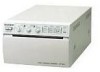
Sony UP895 Service Manual - Page 4

Troubleshooting, Service Mode Self-diagnostic Function, Semiconductor Pin Assignments - paper

Page 4 highlights

4-4. System Control Section 4-8 4-4-1. Reading of Keys 4-8 4-4-2. Reading of Function Switches 4-8 4-4-3. Platen Motor Control 4-9 4-4-4. Head Up and Down Control 4-10 4-4-5. Monitor of Door Sensor 4-10 4-4-6. Monitor of Paper Sensor 4-10 4-4-7. Monitor of Head Temperature Sensor 4-11 4-4-8. Control of Head Fan Motor (for Head Cooling 4-11 4-4-9. Control of Video Circuit Section 4-11 4-4-10. Control of Memory and Head Control Circuit 4-12 4-4-11. Gamma Correction and Thermal Storage Correction 4-13 4-4-12. Discrimination of Video Signal to be Input 4-13 4-4-13. Remote Interface 4-13 4-4-14. Storage of Print Count History 4-13 4-5. Thermal Head Section 4-14 4-5-1. Structure 4-14 4-5-2. Basic Operation 4-15 4-5-3. Stair Generation 4-15 4-5-4. Temperature Correction 4-16 4-5-5. Line Count Correction 4-16 5. Troubleshooting 5-1. Print is Faulty 5-1 5-2. Print is Too Dark or Too Light 5-2 5-3. "Paper Sensor" is Out of Order 5-3 5-4. Head Operation (Up & Down) is Out of Order 5-4 5-5. Paper Feeding is Out of Order 5-5 5-6. Door (Opening and Closing) is Out of Order 5-6 6. Service Mode (Self-diagnostic Function) 6-1 Printing the Test Pattern 6-1 6-2. Up/Down Operation of Head 6-2 6-3. Feed Operation 6-2 6-4. Display and Clearing of Print Sheet History 6-3 7. Semiconductor Pin Assignments 2 UP-895/(E)

  • 1
  • 2
  • 3
  • 4
  • 5
  • 6
  • 7
  • 8
  • 9
  • 10
  • 11
  • 12
  • 13
  • 14
  • 15
  • 16
  • 17
  • 18
  • 19
  • 20
  • 21
  • 22
  • 23
  • 24
  • 25
  • 26
  • 27
  • 28
  • 29
  • 30
  • 31
  • 32
  • 33
  • 34
  • 35
  • 36
  • 37
  • 38
  • 39
  • 40
  • 41
  • 42
  • 43
  • 44
  • 45
  • 46
  • 47
  • 48
  • 49
  • 50
  • 51
  • 52
  • 53
  • 54
  • 55
  • 56
  • 57
  • 58
  • 59
  • 60
  • 61
  • 62
  • 63
  • 64
  • 65
  • 66
  • 67
  • 68
  • 69
  • 70
  • 71
  • 72
  • 73
  • 74
  • 75
  • 76
  • 77
  • 78
  • 79
  • 80
  • 81
  • 82
  • 83
  • 84

2
UP-895/(E)
4-4.
System Control Section
...............................................................................
4-8
4-4-1.
Reading of Keys
.........................................................................
4-8
4-4-2.
Reading of Function Switches
...................................................
4-8
4-4-3.
Platen Motor Control
..................................................................
4-9
4-4-4.
Head Up and Down Control
.....................................................
4-10
4-4-5.
Monitor of Door Sensor
...........................................................
4-10
4-4-6.
Monitor of Paper Sensor
..........................................................
4-10
4-4-7.
Monitor of Head Temperature Sensor
......................................
4-11
4-4-8.
Control of Head Fan Motor (for Head Cooling)
......................
4-11
4-4-9.
Control of Video Circuit Section
.............................................
4-11
4-4-10.
Control of Memory and Head Control Circuit
.........................
4-12
4-4-11.
Gamma Correction and Thermal Storage Correction
..............
4-13
4-4-12.
Discrimination of Video Signal to be Input
.............................
4-13
4-4-13.
Remote Interface
......................................................................
4-13
4-4-14.
Storage of Print Count History
.................................................
4-13
4-5.
Thermal Head Section
...............................................................................
4-14
4-5-1.
Structure
...................................................................................
4-14
4-5-2.
Basic Operation
........................................................................
4-15
4-5-3.
Stair Generation
.......................................................................
4-15
4-5-4.
Temperature Correction
...........................................................
4-16
4-5-5.
Line Count Correction
..............................................................
4-16
5.
Troubleshooting
5-1.
Print is Faulty
..............................................................................................
5-1
5-2.
Print is Too Dark or Too Light
...................................................................
5-2
5-3.
“Paper Sensor” is Out of Order
...................................................................
5-3
5-4.
Head Operation (Up & Down) is Out of Order
...........................................
5-4
5-5.
Paper Feeding is Out of Order
....................................................................
5-5
5-6.
Door (Opening and Closing) is Out of Order
..............................................
5-6
6.
Service Mode (Self-diagnostic Function)
6-1
Printing the Test Pattern
..............................................................................
6-1
6-2.
Up/Down Operation of Head
......................................................................
6-2
6-3.
Feed Operation
............................................................................................
6-2
6-4.
Display and Clearing of Print Sheet History
...............................................
6-3
7.
Semiconductor Pin Assignments