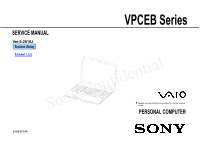
Sony VPCEB16FX/L Service Manual - Page 5

Table Of Con, Ntents - motherboard

Page 5 highlights

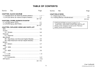
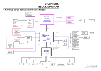
TABLE OF CONTENTS Section Title Page CHAPTER1. BLOCK DIAGRAM 1-1.VPCEB Series (for External Graphic Models 1...-1..1-1 1-2.VPCEB Series (for Internal Graphic Models 1-.2.1-2 (to 1-2) CHAPTER2. FRAME HARNESS DIAGRAM 2-1.VPCEB Series (TOP 2.-12-1 2-2.VPCEB Series (BOTTOM 2.-2-2 (to 2-2) CHAPTER3. EXPLODED VIEWS AND PARTS LIST Note 3-2 Screws S-1. Screws 3..-.3 Palmrest P-1. Palmrest 3....-4 Main Board M-1. Main Board (for External Graphic Models 3..-.5.. M-2. Main Board (for Internal Graphic Models 3..-.6. Bottom B-1. Bottom 3-...7 ODD D-1. ODD 3...-8 HDD H-1. HDD 3...-9... LCD L-1. LCD 3..-.10 Accessories A-1. Accessories 3-...11 DIP Switch 3...-12 (to 3-12) 5 Section Title Page CHAPTER4.OTHERS 4-1. Replacing the CPU 4-1 4-2. Holding Method of Motherboard 4-2 (to 4-2) x SPECIFICATIONS are listed on page 3-1 of "CHAPTER3. EXPLODED VIEWS AND PARTS LIST. x History of the changes is shown as the "Revision History" at the end of this data. [Sony Confidential] VPCEB Series (9-852-873-XX)

  • 1
  • 2
  • 3
  • 4
  • 5
  • 6
  • 7
  • 8
  • 9
  • 10
  • 11
  • 12
  • 13
  • 14
  • 15
  • 16
  • 17
  • 18
  • 19
  • 20
  • 21
  • 22
  • 23
  • 24
  • 25
  • 26
  • 27

TABLE OF CON
Section
Title
Page
CHAPTER1. BLOCK DIAGRAM
1 1 VPCEB Series (for External Graphic Models)
11
11
1-1.VPCEB Series (for External Graphic Models)…………….…..1-1
1-2.VPCEB Series (for Internal Graphic Models)…
....
…..…..…..1-2
CHAPTER2. FRAME HARNESS DIAGRAM
2-1.VPCEB Series (TOP)………………………...………………. 2-1
1-1
1-2
2-1
(to 1-2)
2-2.VPCEB Series (BOTTOM)……………………..……………. 2-2
CHAPTER3. EXPLODED VIEWS AND PARTS LIST
Note……………………………………………………………….…
Screws
2-2
3-2
(to 2-2)
Screws
S-1. Screws………………………………………….……
.........
Palmrest
P-1. Palmrest…………………………………………
.......
…..…
Main Board
M1Mi
B
d (f
E
lG
hi
Mdl)
3-3
3-4
M-1. Main Board (for External Graphic Models)…
....
…..…
.....
M-2. Main Board (for Internal Graphic Models)…
....
…..…
Bottom
B-1. Bottom………………………………………………..………
ODD
3-5
3-6
3-7
ODD
D-1. ODD…………………………………………………………
HDD
H-1. HDD……………………………………………………………
LCD
L 1 LCD
3-8
3-9
3 10
L-1. LCD…………………………
...........................................
Accessories
A-1. Accessories…………………………..…………...…………
DIP Switch………
..................................
...........................
3-10
3-11
3-12
(to 3-12)
(to 3 12)
5
NTENTS
Section
Title
Page
CHAPTER
4
.OTHERS
41R
l
i
th
CPU
41
SPECIFICATIONS are listed on page 3-1 of
4-1. Replacing the CPU ………..……………..………………
4-1
4-2. Holding Method of Motherboard………..…….…………
4-2
(to 4-2)
SPECIFICATIONS are listed on page 3 1 of
“CHAPTER3. EXPLODED VIEWS AND PARTS LIST.
History of the changes is shown as the “Revision
History” at the end of this data.
[Sony Confidential]
VPCEB Series (9-852-873-XX)