Sony VPL EX3 Operating Instructions - Page 49
screen size measured diagonally inches
 |
UPC - 027242689671
View all Sony VPL EX3 manuals
Add to My Manuals
Save this manual to your list of manuals |
Page 49 highlights
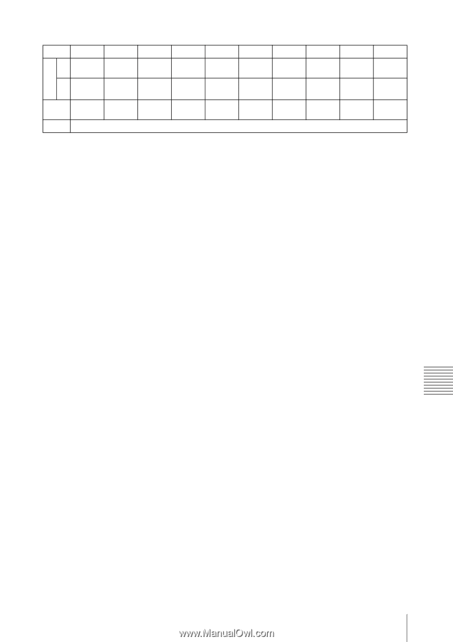
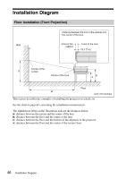
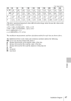
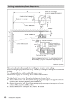
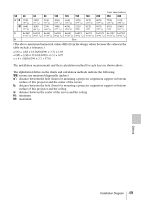
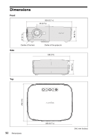
Unit: mm (inches) SS 40 60 80 100 120 150 180 200 250 300 a' N 1220 (48 1/8) 1820 (71 3/4) 2430 (95 3/4) 3040 3640 4550 5470 6070 7590 9110 (119 3/4) (143 3/8) (179 1/4) (215 1/2) (239 1/8) (298 7/8) (358 3/4) M 1440 (55 1/8) 2090 (82 3/8) 2790 3490 4180 5230 (109 7/8) (137 1/2) (164 5/8) (206) 6270 (247) 6970 8710 (274 1/2) (343) 10450 (411 1/2) x b+260 b+362 b+463 b+565 b+667 b+819 b+971 b+1073 b+1327 b+1581 (b+10 1/4) (b+14 3/8) (b+18 1/4) (b+22 1/4) (b+26 3/8) (b+32 1/4) (b+38 1/4) (b+42 1/4) (b+52 1/4) (b+62 1/4) b Free (The above-mentioned numerical values differ from the design values because the values in the table include a tolerance.) a'(N) = {(SS × 18.56/0.6299) + 3.3} × 1.03 a'(M) = {(SS × 22.61/0.6299) +3.3} × 0.97 x = b + (SS/0.6299 × 3.2 + 57.0) The installation measurements and their calculation method for each lens are shown above. The alphabetical letters in the charts and calculation methods indicate the following. SS: screen size measured diagonally (inches) a': distance between the hole (front) for mounting a projector suspension support on bottom surface of this projector and the center of the screen b: distance between the hole (front) for mounting a projector suspension support on bottom surface of this projector and the ceiling x: distance between the center of the screen and the ceiling N: minimum M: maximum Others Installation Diagram 49
-
 1
1 -
2
-
3
-
4
-
5
-
6
-
7
-
8
-
9
-
10
-
11
-
12
-
13
-
14
-
15
-
16
-
17
-
18
-
19
-
20
-
21
-
22
-
23
-
24
-
25
-
26
-
27
-
28
-
29
-
30
-
31
-
32
-
33
-
34
-
35
-
36
-
37
-
38
-
39
-
40
-
41
-
42
-
43
-
 44
44 -
 45
45 -
 46
46 -
 47
47 -
 48
48 -
 49
49 -
 50
50 -
 51
51 -
 52
52 -
 53
53
 |
 |