Sony XCL5005 Specification Sheet (XCL-5005 / 5005CR Spec Sheet) - Page 2
Dimensions, Specifications, PIN Assignment &, Connector, Optional Accessories - xcl 5005
 |
View all Sony XCL5005 manuals
Add to My Manuals
Save this manual to your list of manuals |
Page 2 highlights
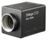
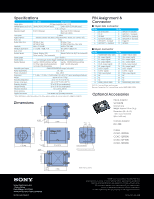
Specifications Image device Standard picture size (H x V) Cell size Resolution depth Lens mount Digital interface Frame rate Output data clock Sensitivity Minimum illumination Gain control Readout modes Shutter speed Shutter mode Readout features Extended signal output Power requirements Power consumption Dimensions Weight Operating temperature Storage temperature Operating humidity Storage humidity Vibration resistance Shock resistance Supplied accessories XCL-5005 XCL-5005CR 2/3-type progressive scan IT CCD 2448 x 2050 (5,018,400 pixels) 2448 x 2050 (5,018,400 pixels)* 3.45 x 3.45 µm 8/10/12 bits/pixel Raw Color: 8/10/12 bits/pixel RGB Color: 24bits C mount Standard Camera Link (Base Configuration)/PoCL (Power over Camera Link) 15 fps 80 MHz (1 Tap) 80 MHz (1 Tap) 40 MHz (2 Taps) 40 MHz (2 Taps, Raw Color only) 400 lx F5.6 (0dB) 2000 lx F5.6 (0dB) 1 lx (GAIN +18dB, F1.4) 8 lx (GAIN +18dB, F1.4) 0 to +18 dB Normal, Binning (1x2), Normal, Partial scan (by 2 line increments) Partial scan (by 1 line increments) 2 to 1/10,000 s External trigger shuter (Trigger start/Trigger start and exposure duration) Gamma : OFF/ON (Arbitrary setting), Gamma : OFF/ON (Arbitrary setting) DTL filter (Edge detection/emphasis), AWB : OFF/ON (One push) 3x3 matrix filter, Binarization DVAL/EXPOSURE/GND output (selectable) DC 12V Max. 3.8 W 1 3/4 (W) x 1 3/4 (H) x 2 3/8 (D) inches ( 44 x 44 x 57.5 mm), (excluding protrusions) Approx. 4.6 oz (130 g) 23 to 113 °F (-5 to 45 °C) -22 to 140 °F (-30 to 60 °C) 20 to 80 % (no condensation) 20 to 95 % (no condensation) 10 G (20 to 200 Hz) 70 G Lens mount cap, Operating instructions * When RAW data is output, depending on the frame grabber, picture size may be reduced to 2,446 (H) x 2,048 (V). PIN Assignment & Connector ■ 12-pin EIAJ connector Pin No. 1 DC IN (Ground) 2 DC IN 3 ISO GND 4 Store OUT (Isolated) 5 GPIO OUT 1- (Isolated) 6 GPIO OUT 1+ (Isolated) Pin No. 7 GPIO IN 1+ (Isolated) 8 GPIO OUT 2- (Isolated) 9 GPIO OUT 2+ (Isolated) 10 GPIO OUT 2+ (Isolated) 11 Trigger IN 12 ISO GND ■ 26-pin connector Pin No. Pin No. 1 POWER/INNER_SHIELD (GND) 14 INNER_SHIELD (GND) 2 X0- output (signal) 15 X0+ output (signal) 3 X1- output (signal) 16 X1+ output (signal) 4 X2- output (signal) 17 X2+ output (signal) 5 XCLK- output (signal) 18 XCLK+ output (signal) 6 X3- output (signal) 19 X3+ output (signal) 7 SerTC+ (signal) 20 SerTC- (signal) 8 SerTFG- (signal) 21 SerTFG+ (signal) 9 TRIG- input (signal) 22 TRIG+ input (signal) 10 NC 23 NC 11 NC 24 NC 12 NC 25 NC 13 INNER_SHIELD (GND) 26 POWER/INNER_SHIELD (GND) PoCL: Pin 1 and pin 26 are used for power. Standard Camera Link: Pin 1 and pin 26 are used for INNER_SHIELD (GND). Optional Accessories Dimensions 1 1/16 (26) Tripod Adaptor VCT-ST70I Isolated type Weight: Approx. 0.5 oz (14 g) Dimensions (W x H x D): 1 5/8 x 1/4 x 2 3/8 inches (40 x 6 x 59 mm) 4-M3 17/32 (13) 2 (50) 13/32 1/2 (10) (12) Camara Adaptor DC-700 1 3/4 (44) 1 3/16 (ø 28.7) 1 3/4 (44) 11/32 (8) 4-M3 2 3/8 (57.5) 12-Pin Connector 26-Pin Camera Link Connector Cables CCXC-12P02N CCXC-12P05N CCXC-12P10N CCXC-12P25N 1 1/16 (26) 17/32 (13) 2 (50) Sony Electronics Inc. 1 Sony Drive Park Ridge, NJ 07656 www.sony.com/videocameras IS-1206 (MK10466V1) Unit: inches (mm) ©2008 Sony Corporation. All rights reserved. Reproduction in whole or in part without written permission is prohibited. Features and specifications are subject to change without notice. All non-metric weights and measurements are approximate. Sony is a registered trademark of Sony Corporation. All other trademarks are the property of their respective owners. Printed in U.S.A. 2/08
-
 1
1 -
 2
2
 |
 |
